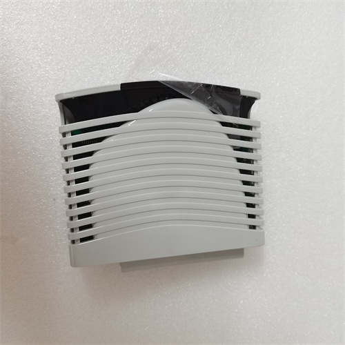
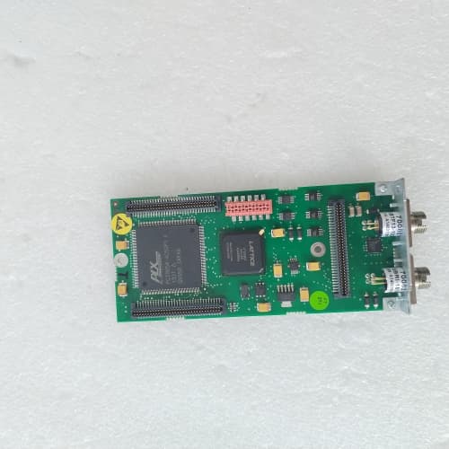
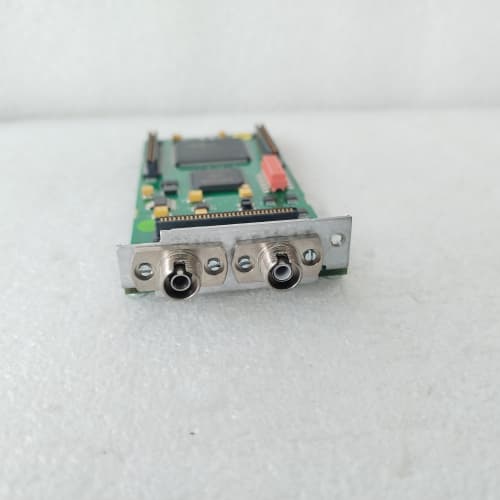
ABB TA524 is a multi-functional industrial automation module that integrates temperature measurement control and PROFIBUS DP redundant bus conversion capabilities, designed for seamless integration into complex PLC and DCS systems. It supports multiple types of temperature sensors including thermocouples and RTDs, enabling accurate temperature monitoring in industrial processes while realizing bidirectional conversion between single bus and redundant dual PROFIBUS DP buses. ABB TA524 features 6 dual-color LED status indicators for real-time monitoring of bus links and power conditions, with relay output alarms for fault notification. Its rugged industrial-grade design with IP30 protection and wave-patterned aluminum reinforced housing ensures reliability in harsh industrial environments. ABB TA524 also offers flexible interface options including 1-2 PROFIBUS DP electrical ports and 1-2 155M optical fiber interfaces, supporting long-distance data transmission up to 20km for large-scale industrial facilities.
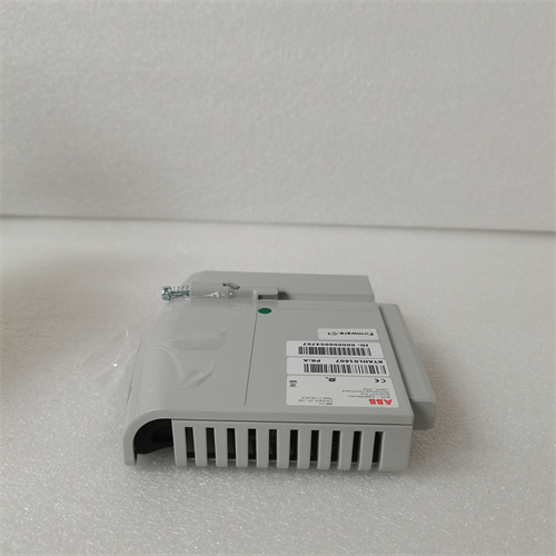
ABB CAI04 is a multi-functional I/O interface module designed for industrial automation systems, serving as a core link between sensors, actuators, and controllers in complex industrial environments. ABB CAI04 integrates 16 digital input and 16 digital output channels, supporting both single-ended and differential input types with relay outputs for direct control of field devices. ABB CAI04 features multi-protocol compatibility including Profibus, Modbus, and EtherCAT, enabling seamless integration with ABB PLCs and third-party automation systems like Siemens S7 series. ABB CAI04 delivers high processing speed of 550μs and 50kHz output frequency, ensuring real-time response for time-sensitive industrial processes. ABB CAI04 supports DIN rail or rack mounting for flexible installation in control cabinets, with built-in safety mechanisms to resist external interference and ensure system stability. ABB CAI04 offers remote diagnostic and maintenance capabilities, reducing on-site downtime and simplifying system management for manufacturing and processing industries.
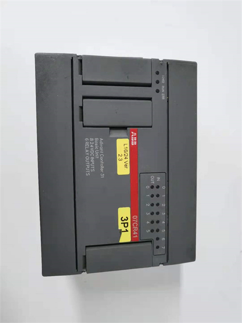
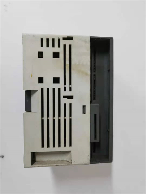
ABB 07CR41 is a digital I/O basic unit for ABB Advant Controller 31 (AC31) PLC systems, featuring 8×24V DC digital inputs and 6×relay outputs with a CS31 system bus interface for seamless integration. ABB 07CR41 delivers reliable I/O control with built-in overload and short-circuit protection, plus LED diagnostic indicators for quick status checks. Its compact design and DIN – rail/screw – mount compatibility let ABB 07CR41 fit easily into space – constrained control cabinets. ABB 07CR41 also offers robust electrical isolation and IP20 protection, making it suitable for harsh industrial settings like manufacturing lines and process control stations. With low power consumption and plug – and – play CS31 bus integration, ABB 07CR41 minimizes deployment time and operational costs while ensuring stable long – term performance.
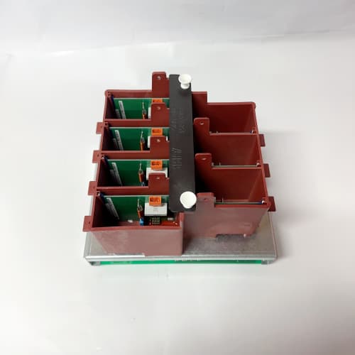
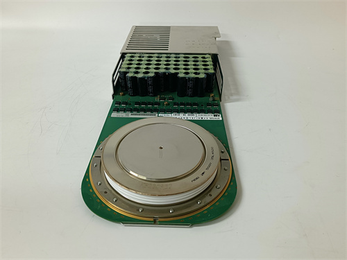
ABB 3BHB003689 is a high-performance IGBT power module, core to ABB’s power electronics portfolio, designed for high-voltage converters, SVG static var generators, and wind power converters. ABB 3BHB003689 excels in power conversion and regulation, enabling efficient industrial equipment drives and grid power quality management in harsh industrial settings. ABB 3BHB003689 integrates comprehensive protection mechanisms including temperature monitoring and overcurrent protection, ensuring long-term stable operation even in extreme temperature ranges. ABB 3BHB003689 supports multi-protocol communication such as Modbus and Profibus, facilitating seamless integration with ABB ACS6000 inverters and third-party power control systems. ABB 3BHB003689 features a water-cooled heat dissipation design, adapting to high-temperature industrial environments like steel mill workshops while maintaining low energy loss. ABB 3BHB003689 is a trusted original spare part for equipment maintenance and replacement, preserving system electromagnetic compatibility and avoiding operational failures.
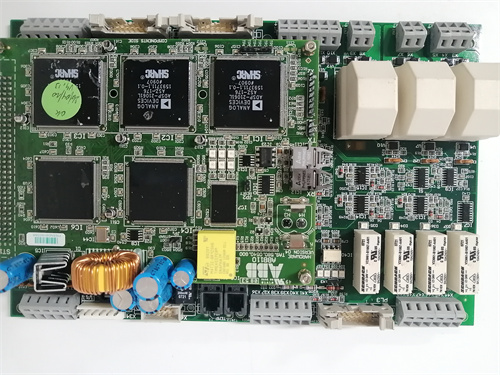
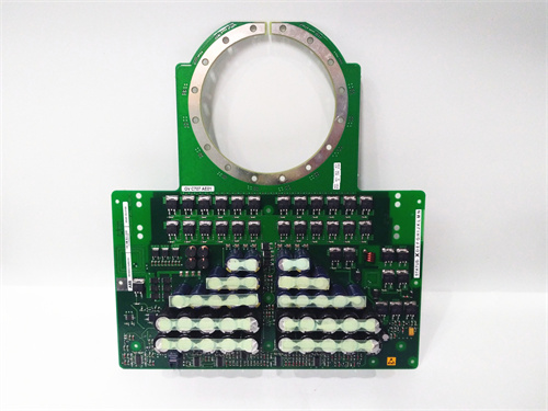
ABB 3BHB003154R0101 is a high-performance IGBT gate drive board (also known as 5SXE05-0156) designed for ABB ACS800 series inverters, specializing in amplifying low-voltage PWM signals to reliably drive IGBT modules in high-power industrial applications. It integrates high-voltage electrical isolation between strong and weak currents, protecting low-voltage control circuits from interference and damage. ABB 3BHB003154R0101 features microsecond-level short-circuit protection and undervoltage protection, with real-time fault feedback to the main control board for quick troubleshooting. Its multi-protocol compatible communication interfaces enable seamless integration into heterogeneous automation environments, while the compact design supports easy assembly in inverter cabinets. ABB 3BHB003154R0101 also incorporates certified “on-board safety” technology, reducing engineering efforts for machine safety compliance and ensuring stable operation across diverse industrial scenarios.
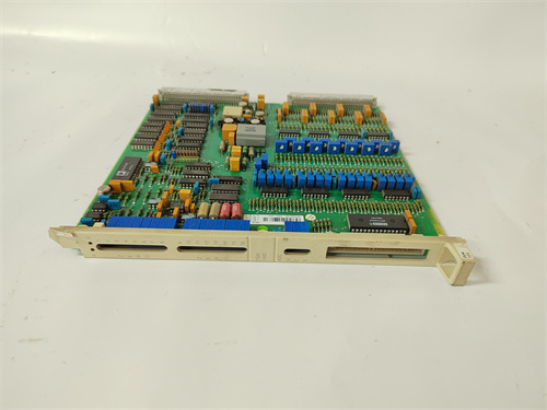
ABB DSAI130D (order code 3BSE003127R1) is a high-precision analog input module from the ABB S100 I/O series, designed for reliable signal acquisition and conversion in industrial automation systems. ABB DSAI130D features 8 single-ended input channels that support standard industrial signals including 4-20mA current and ±10V voltage, meeting diverse process measurement needs. ABB DSAI130D adopts a 16-bit A/D converter with ±0.1% FS accuracy and fast 1000sps sampling rate, ensuring precise and real-time data capture for critical control processes. ABB DSAI130D supports multi-protocol communication such as Profibus DP and Modbus TCP/IP, enabling seamless integration with ABB Advant OCS, S100 I/O systems, and third-party PLCs. ABB DSAI130D boasts robust anti-interference capability and an IP67 protection rating, making it suitable for harsh industrial environments with temperature fluctuations and electromagnetic interference. ABB DSAI130D features DIN rail mounting for easy installation and space-saving in control cabinets, simplifying system expansion and maintenance.
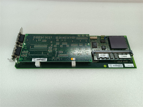
ABB N93-3005-05 1MRK002311-AAR11 is a high-integration control system card module designed for industrial automation and process control, delivering reliable real-time data processing and signal conversion for critical applications. It supports multiple industrial communication protocols including Modbus TCP/IP, IEC 60870-5-103, and DNP3, enabling seamless integration with diverse PLC, DCS, and SCADA systems. ABB N93-3005-05 1MRK002311-AAR11 features built-in arc protection and long-distance data transmission capabilities, making it suitable for large-scale industrial facilities requiring stable signal transfer across extended distances. Its compact design and broad compatibility allow ABB N93-3005-05 1MRK002311-AAR11 to fit into existing control racks without extensive modifications, supporting applications from power distribution to manufacturing automation. ABB N93-3005-05 1MRK002311-AAR11 also incorporates robust fault tolerance and diagnostic functions, ensuring operational continuity and easy maintenance in harsh industrial environments.
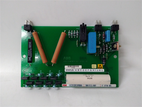
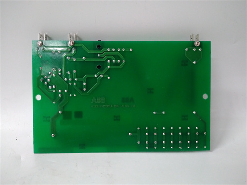
ABB XTB750B01 is a high-reliability digital output plug-in module tailored for ABB industrial control systems, engineered for precise switching control of field actuators in harsh industrial settings. ABB XTB750B01 features 8 independent relay output channels, each rated at 3A/250V AC to drive valves, contactors, and indicator lights without external power amplifiers. ABB XTB750B01 integrates 2500V AC channel-to-channel isolation and overload/short-circuit protection, safeguarding against electrical surges in high-EMI environments like power plants and refineries. ABB XTB750B01 communicates via RS-485 Modbus RTU, enabling seamless data exchange with ABB AC800M controllers and third-party PLCs such as Rockwell ControlLogix. ABB XTB750B01 delivers a fast 0.5ms typical switch time and built-in self-diagnostics for open/short circuit detection, minimizing downtime in critical processes. ABB XTB750B01 has a compact DIN – rail – mountable design and a wide – 20℃ to 60℃ operating temperature range, fitting easily into dense control cabinets while enduring extreme ambient conditions.
ABB 5SHY35L4520 5SXE10-0181 AC10272001R0101 is a high-performance IGCT (Integrated Gate Commutated Thyristor) module designed for medium-frequency and high-voltage power electronic applications, delivering exceptional power density and efficiency. It integrates advanced digital signal processing technology to enable fast fault detection and protection, making it suitable for critical systems like HVDC (High-Voltage Direct Current) transmission and industrial automation. ABB 5SHY35L4520 5SXE10-0181 AC10272001R0101 supports multi-protocol communication including IEC 61850 and Modbus, facilitating seamless integration with DCS/PLC systems for remote monitoring and configuration. Its rugged design with enhanced thermal management ensures stable operation in harsh industrial environments, while built-in protection functions safeguard against overcurrent, overvoltage, and overheating. ABB 5SHY35L4520 5SXE10-0181 AC10272001R0101 also offers programmable logic capabilities, allowing users to customize protection and control strategies to match specific application requirements.
ABB 3BUS208796-501 is a high-performance communication protocol gateway module from ABB’s industrial automation portfolio, dedicated to real-time data exchange and protocol conversion between heterogeneous industrial control systems. ABB 3BUS208796-501 supports bidirectional conversion among PROFINET, Modbus TCP/IP, EtherNet/IP, and Modbus RTU, enabling seamless communication between ABB AC800M controllers and third-party PLCs (e.g., Siemens S7-1500, Rockwell ControlLogix). ABB 3BUS208796-501 is equipped with dual redundant Gigabit Ethernet ports and RS-485/RS-232 serial interfaces, ensuring uninterrupted data transmission in high-availability industrial environments. ABB 3BUS208796-501 features 2500V AC channel isolation and 6kV surge protection, maintaining signal integrity in high-EMI settings without external safety barriers. ABB 3BUS208796-501 integrates a built-in web server for remote configuration and diagnostics, supporting firmware updates without system downtime. ABB 3BUS208796-501 has a wide operating temperature range of -40°C to 70°C and IP20 protection, making it suitable for harsh industrial sites like power plants and petrochemical facilities.
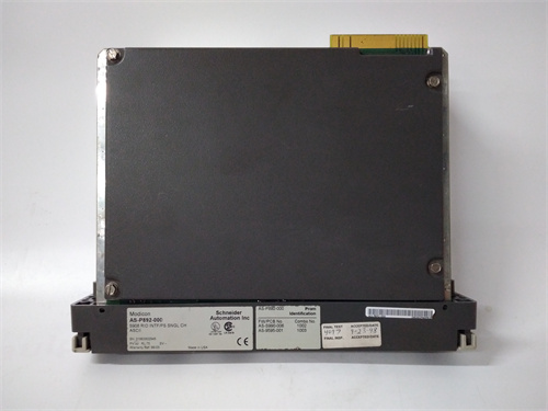
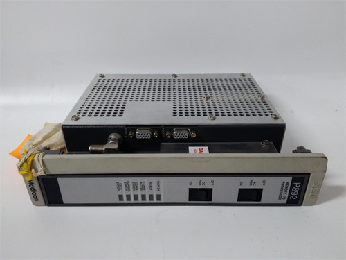
ABB P8151B is a high-reliability digital I/O module tailored for ABB Plantguard safety PLC systems, designed to collect digital switch/pulse signals and drive actuators like contactors and solenoid valves. It integrates seamlessly with Plantguard racks for flexible I/O expansion, supporting mixed 24 VDC inputs/outputs with channel-level isolation to avoid cross-talk. ABB P8151B uses a 32-bit processor for real-time data handling and non-volatile memory for fault logging, ensuring data integrity during power cycles. ABB P8151B supports Modbus TCP, EtherNet/IP, and Profibus for easy DCS/PLC integration, and its hot-swappable design enables online maintenance without system shutdown. ABB P8151B also features channel diagnostics and overvoltage protection, making it ideal for safety-critical industrial processes requiring SIL 3 compliance.
ABB AI625 is a high-precision analog input module from the ABB S800 I/O series, designed for accurate signal acquisition and conversion in industrial process control systems. ABB AI625 supports 8 configurable channels (single-ended or differential via DIP switch) and is compatible with standard industrial signals such as 4-20mA current, 0-10V voltage, and Pt100/Cu50 thermocouples, meeting diverse measurement needs. ABB AI625 features a 16-bit Δ-Σ ADC converter with a 10kHz per-channel conversion rate, delivering exceptional measurement accuracy of ±0.05% FS and minimal temperature drift of ±0.001% FS/℃. ABB AI625 integrates 2500V AC channel isolation and 6kV surge protection, ensuring signal integrity in high-EMI industrial environments without the need for external safety barriers. ABB AI625 communicates via PROFINET or Modbus RTU, enabling seamless integration with ABB AC800M controllers and third-party PLCs like Siemens S7-1200. ABB AI625 includes built-in wire break detection and configurable over-range alarms, providing real-time fault feedback for critical process monitoring.

.jpg)