GE UR6DH is a high-reliability digital I/O module belonging to GE Multilin’s Universal Relay series, designed for industrial automation control, power system monitoring, and auxiliary device management. It integrates 16 contact inputs and versatile output configurations, supporting 24–48VDC power supply to adapt to diverse industrial power requirements. GE UR6DH features programmable logic and serial communication interfaces (RS-232, RS-485) along with industrial protocols like Modbus TCP/IP, Ethernet/IP, and PROFINET IO, enabling seamless integration with universal relays, PLCs, and DCS systems without complex hardwiring. Its 2,500VDC channel isolation enhances safety in high-voltage environments, while fail-safe operation ensures system integrity during unexpected disruptions. GE UR6DH adopts a compact modular design (100mm×100mm×25mm) for DIN rail mounting, simplifying installation and expansion in control panels. With a wide operating temperature range of -40°C to +70°C and compliance with industrial EMC standards, GE UR6DH excels in power distribution, substation automation, and manufacturing applications requiring robust and flexible I/O control.
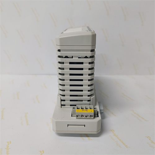
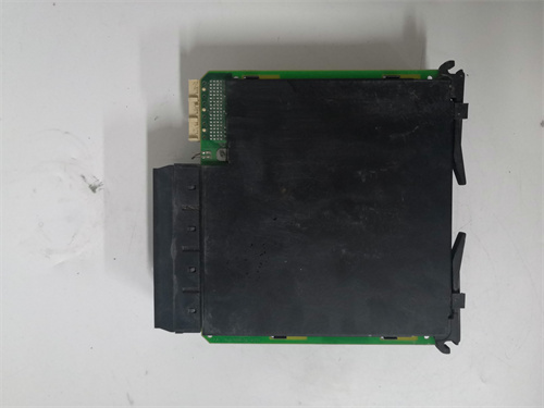
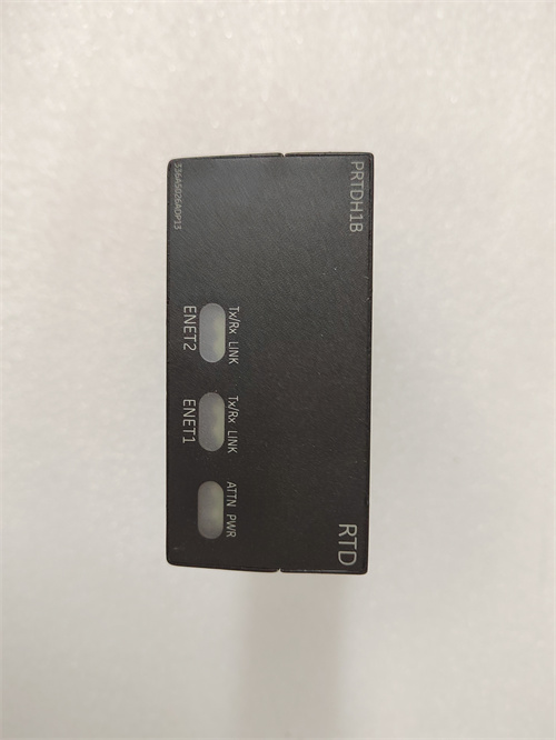
GE IS220PRTDH1BC 336A5026ADP13 is a high-performance RTD input module under GE’s PACSystems RX3i and Mark VIe Speedtronic product lines, specializing in precise temperature signal acquisition and processing for industrial automation systems. GE IS220PRTDH1BC 336A5026ADP13 collects signals from resistance temperature sensors (RTDs) such as Pt100 and Pt1000, converting analog temperature data into digital signals for real-time transmission to upper-level PLC/DCS systems. GE IS220PRTDH1BC 336A5026ADP13 supports seamless integration with GE’s PACSystems RX3i, Mark V, and Mark VIe Speedtronic control platforms, as well as process protection systems in power plants and refineries. GE IS220PRTDH1BC 336A5026ADP13 features built-in digital filtering and self-diagnostic functions, minimizing noise interference and enabling quick fault identification in harsh industrial environments. GE IS220PRTDH1BC 336A5026ADP13 adopts a modular design with plug connections, facilitating easy installation, maintenance, and hot-swapping without system shutdown.
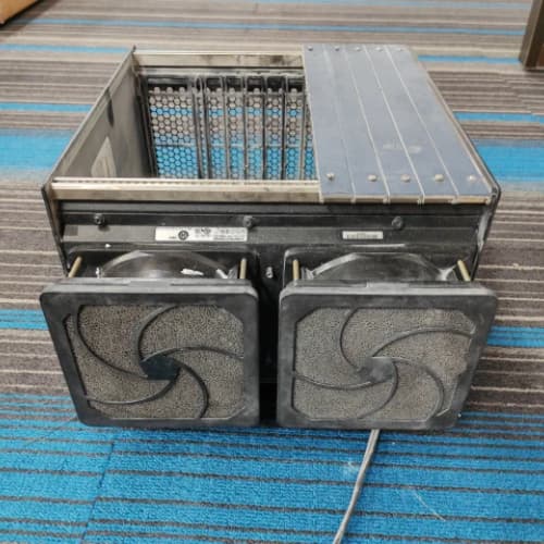
GE IC698CHS117C is a 17-slot front-mount rack for GE PACSystems RX7i, serving as the backbone for CPU, I/O, and VME module integration in industrial automation systems. It uses a VME64 backplane with 0.8-inch slot spacing, supporting single/double-width RX7i, Series 90-70, and standard VME modules. GE IC698CHS117C features slot sensing and software-based configuration, eliminating DIP switches/jumpers for faster setup. Slot 0 houses the power supply, slot 1 (or 1-2 for double-width CPUs) holds the CPU, and the remaining slots accommodate up to 15 single-width or 8 double-width I/O modules. GE IC698CHS117C supports 350W high-wattage RX7i power supplies, delivering 60A at +5V, 12A at +12V, and 4A at -12V for stable module operation. Its rugged design and broad compatibility make GE IC698CHS117C ideal for power generation, manufacturing, and process control applications requiring scalable I/O expansion and reliable backplane communication.
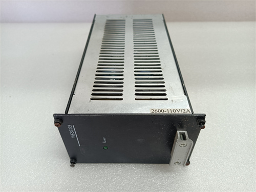
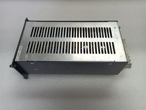
GE WES5120 2340-21005 is a dedicated digital input module under GE’s WES5120 series, serving as a critical data acquisition component in industrial automation systems. GE WES5120 2340-21005 specializes in collecting and transmitting digital signals from sensors, switches, and field devices, enabling real-time monitoring and control for PLC and DCS systems. GE WES5120 2340-21005 supports seamless integration with GE’s 90-30/90-70 PLC series, PACSystems RX3i, and VersaMax control platforms, ensuring compatibility with existing GE automation ecosystems. GE WES5120 2340-21005 adopts industrial-grade components and robust protection mechanisms, delivering stable performance in harsh environments with extreme temperatures and electromagnetic interference. GE WES5120 2340-21005 features a modular design for easy installation and maintenance, reducing on-site deployment time and operational costs for industrial users.
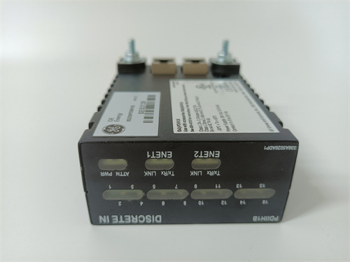
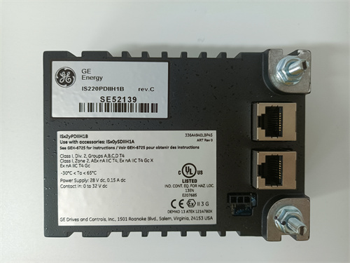
GE IS220PDOAH1A is a discrete output pack (PDOA) designed for the GE Speedtronic Mark VIe turbine control system, serving as a critical interface between I/O Ethernet networks and discrete output terminal boards. It integrates a shared Mark VIe processor board and a dedicated discrete output acquisition board, controlling up to 12 relays (electromagnetic or solid – state, based on terminal board type) and receiving terminal – board – specific feedback. GE IS220PDOAH1A uses dual RJ45 Ethernet ports for high – speed communication, a 3 – pin power input, and a DC – 37 pin connector for direct terminal board output. It features LED status indicators (Power, Attention, TxRx, Link) and an infrared port for local diagnostic serial communication, enabling quick troubleshooting. GE IS220PDOAH1A supports system redundancy, ensuring continuous operation during network or power disruptions, and is ideal for power generation, oil and gas, and industrial turbine control applications where reliable discrete output control is essential.
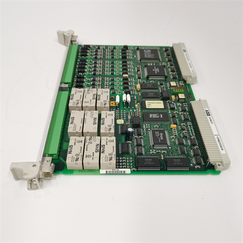
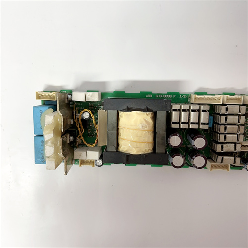
ABB EHDB280 is a multi-functional industrial automation module, serving as a core component for control logic execution, signal conversion, and system integration in diverse industrial scenarios. ABB EHDB280 features 8 digital input and 8 digital output channels, supporting seamless connection with sensors, actuators, and motors while enabling real-time data processing and control commands. ABB EHDB280 supports multiple communication protocols including Modbus RTU, TCP/UDP, RS232, and RS485, ensuring compatibility with ABB DCS/PLC systems and third-party automation equipment. ABB EHDB280 offers IP67 high protection rating and wide operating temperature range, withstanding dust, water splashes, and extreme temperatures in harsh industrial environments. ABB EHDB280 integrates comprehensive motor protection functions such as overload, undervoltage, single-phase operation, and overheating protection, safeguarding critical equipment from damage. ABB EHDB280 adopts a modular and compact design, supporting flexible installation and easy maintenance, making it suitable for both new system deployment and existing system upgrades.
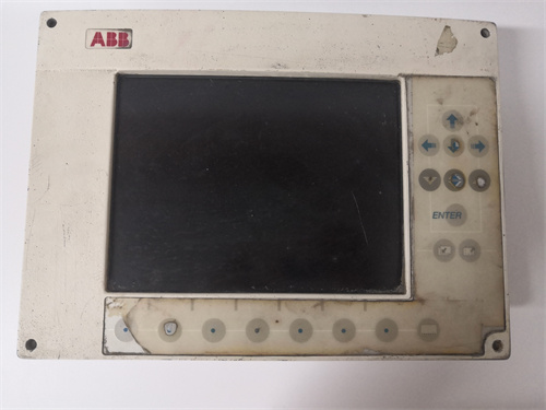
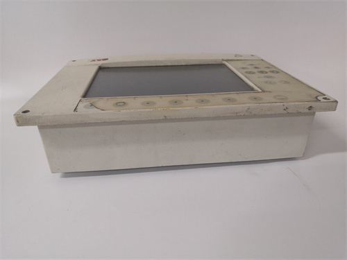
ABB GOP2 is a high-performance human – machine interface (HMI) operator panel tailored for ABB industrial control systems, acting as a core interactive hub for real – time process monitoring, equipment control, and fault diagnosis. It is fully compatible with ABB T800 and AC 800M systems, and can seamlessly connect with PLCs, DCS, and field devices via multiple industrial protocols. ABB GOP2 is equipped with a 10.4 – inch high – resolution display and an ARM Cortex – A9 processor, enabling fast response to operational commands and clear presentation of complex process data. It has 512MB RAM and 512MB flash memory, which can store large – scale HMI projects and historical data, supporting functions such as trend analysis and alarm logging. ABB GOP2 is designed with an industrial – grade structure, featuring IP65 front – panel protection and dual 24VDC power input, which can operate stably in harsh industrial environments with large temperature fluctuations and strong electromagnetic interference. Its flexible communication interfaces, including Ethernet, USB, RS232, and RS485, make ABB GOP2 an ideal choice for manufacturing, energy, and water treatment industries, ensuring efficient human – machine interaction and reliable system operation.
ABB DSMC112 57360001-HC is a specialized floppy disk controller module from ABB’s MasterPiece 200 series, designed for data management in industrial automation systems. ABB DSMC112 57360001-HC enables reading, writing, saving, and backing up programs by interacting with floppy disk drives, serving as a critical data transfer link in ABB PLC and DCS systems. ABB DSMC112 57360001-HC supports data conversion between bit formats and MFM/GCR recording formats, with built-in cyclic redundancy check (CRC) for error detection during data transmission. ABB DSMC112 57360001-HC features multiple communication interfaces including Ethernet and serial ports, facilitating seamless data exchange with other automation equipment. ABB DSMC112 57360001-HC adopts modular design and supports diverse installation methods, adapting to control cabinets of different sizes in manufacturing and energy sectors. ABB DSMC112 57360001-HC uses high-quality components and undergoes strict quality testing, ensuring long-term stable operation in complex industrial environments.
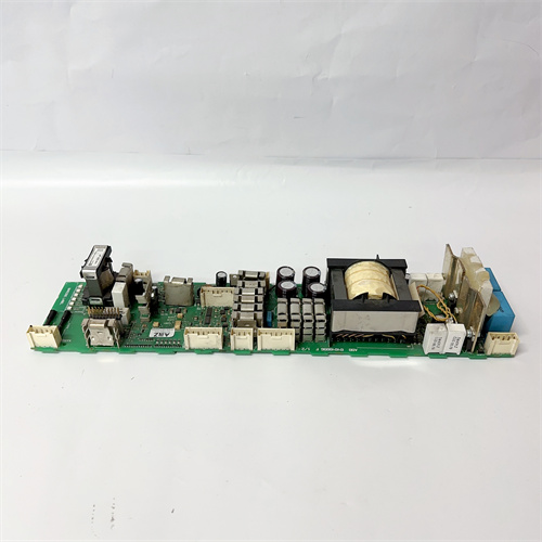
ABB PFSK151 is a multi-functional programmable controller module designed for ABB AC 800M control systems, integrating data acquisition, signal processing, communication, and safety control to meet diverse industrial automation needs. It features a flexible I/O configuration with 8 basic inputs and 6 outputs, expandable up to 142 I/O points, enabling connection with various sensors and actuators for precise process control. ABB PFSK151 supports multiple industrial protocols including Profibus, Modbus, TCP/IP, and EtherNet/IP, plus communication interfaces like Ethernet (RJ45) and RS-485 for seamless integration with PLC, DCS, and SCADA systems. Its industrial-grade design includes IP20 protection, strong anti-interference capabilities, and dual 24VDC power options, ensuring reliable operation in harsh environments with temperature fluctuations and electromagnetic interference. ABB PFSK151 also incorporates safety functions such as emergency stop and door lock interlocking, along with non-volatile memory to retain critical data during power outages, making it versatile for manufacturing, energy, and chemical sectors.
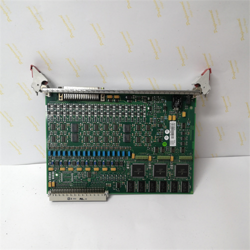
ABB AI880-1 is a high-integrity analog input module from the ABB S800 I/O series, designed for precision signal acquisition in industrial automation and safety-critical control systems. ABB AI880-1 features 8 independent current input channels, supporting 4-20mA and 0-20mA standard signals to connect temperature, pressure, and flow sensors seamlessly. ABB AI880-1 integrates HART pass-through communication and external transmitter power distribution, simplifying wiring for 2-wire or 3-wire transmitters while enabling remote device configuration. ABB AI880-1 holds SIL3 certification per IEC 61508 and Category 4 certification per EN 954-1, ensuring reliability for emergency shutdown and safety control systems. ABB AI880-1 offers channel-to-ModuleBus isolation and 1000V surge protection, withstanding electromagnetic interference in harsh industrial environments. ABB AI880-1 supports seamless integration with ABB Advant OCS, AC800M controllers, and third-party systems, with user-configurable overrange and underrange limits for flexible application adaptation.
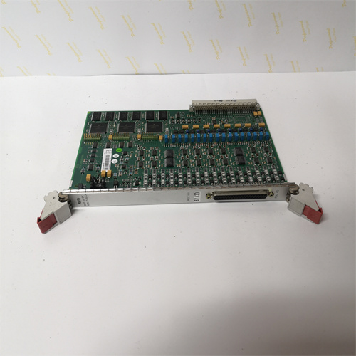
ABB 3ASC25H204 (part of the DAPU100 series) is a high-performance processor module designed for ABB AC500 PLC and distributed control systems (DCS), serving as the core “brain” for complex industrial automation tasks. It integrates 32-bit high-speed processing, multi-protocol communication, and digital I/O signal interaction, supporting IEC 61131-3 standard programming languages for flexible logic control and data processing. ABB 3ASC25H204 features dual independent communication interfaces (Ethernet and Profibus-DP/RS485) and supports Modbus TCP, Ethernet/IP, and Profibus protocols, enabling seamless integration with SCADA, HMI, and field devices. Its industrial-grade design includes 2MB battery-backed program memory, hardware watchdog, and hot-swappable functionality, ensuring reliable operation in harsh environments with temperature fluctuations and electromagnetic interference. ABB 3ASC25H204 also integrates a pressure compensation system to adapt to atmospheric pressure and backpressure changes, making it suitable for emission compliance monitoring in process industries.
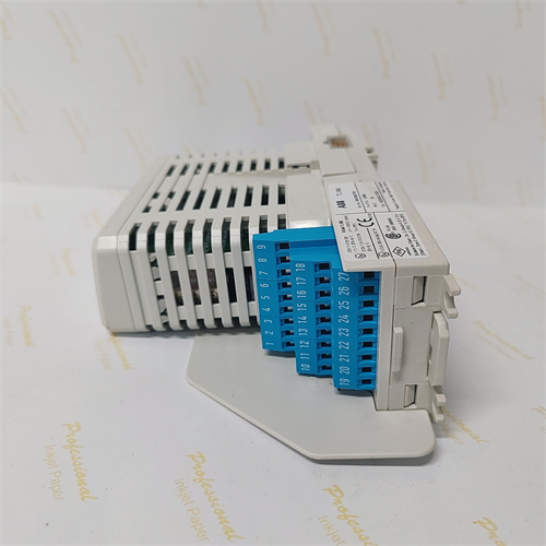
ABB TU810V1 (sub-model 3BSE013230R1) is a compact module terminal unit (MTU) for ABB S800 I/O systems, serving as a core link between field devices and control modules in industrial automation. ABB TU810V1 offers 16-channel 50V signal interfaces, supporting mixed access of digital (dry/wet contacts) and analog (0-10V/4-20mA) signals to connect sensors, transmitters, and actuators simultaneously. ABB TU810V1 uses ModuleBus for signal distribution and address generation, supporting cascade expansion of up to 32 units to meet large-scale signal access needs. ABB TU810V1 features dual mechanical locks with 36 configuration combinations, preventing incorrect module insertion through physical limits. ABB TU810V1 integrates dual-layer electromagnetic shielding and wide-temperature components, withstanding harsh industrial environments such as high interference and corrosion. ABB TU810V1 supports hot-swapping and remote configuration, seamlessly integrating with ABB AC800M controllers, Symphony Plus DCS, and third-party PLC systems.

.jpg)