
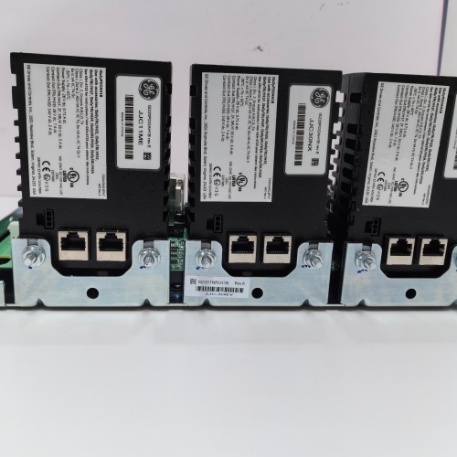
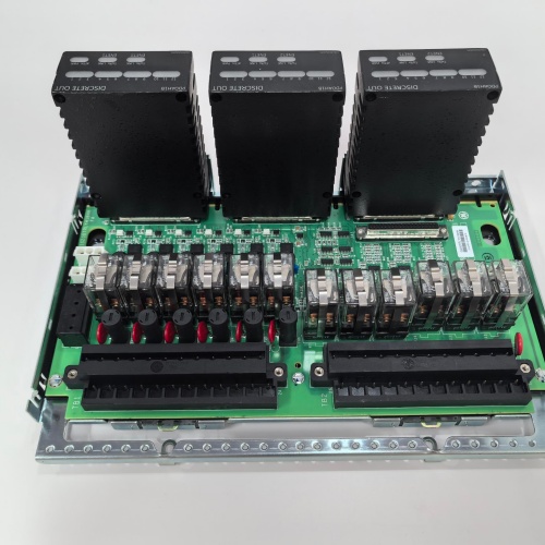
Description
Key Specifications
| Parameter | Specification |
|---|---|
| Output Channels | 16 Form A (normally open) relay outputs |
| Contact Rating | 5 A @ 250 VAC / 30 VDC (resistive load) |
| Inrush Capability | 10 A for 100 ms (inductive/capacitive loads) |
| Coil Voltage | 24 VDC nominal (module powered) |
| Switching Frequency | Maximum 10 Hz (mechanical life limitation) |
| Mechanical Life | >10,000,000 operations (no load) |
| Electrical Life | >100,000 operations at rated load |
| Protection | Built-in flyback diodes (for DC inductive loads), snubber circuits (for AC loads — optional external) |
| Diagnostic Feedback | Output state feedback (verifies relay contact closure via auxiliary contact) |
| Isolation | 1500 VDC (coil-to-contacts), 1000 VDC (contact-to-contact) |
| Communication | I/O Net (dual Ethernet ports for redundancy) |
| Form Factor | 6U VME64x (160 × 233 mm), single-slot width |
| Indicators | Per-channel LED (output state/command), module health, communication status |
| Operating Temp | 0 °C to +60 °C |
| Power Draw | 8 W (+5 V / +3.3 VDC) — coil power derived from backplane |
| Connectors | Front-panel 32-pin terminal block with captive washer screws |
| Diagnostic Memory | Non-volatile fault logging — stores last 500 events with timestamps |
Advantages & Distinctive Features
-
High-Capacity Relay Outputs: 16 individually isolated Form A relays with 5 A contact rating—controls a wide range of field devices directly.
-
High Inrush Capability: 10 A for 100 ms handles solenoid and motor starting surges.
-
Contact Status Feedback: Each relay includes an auxiliary contact for output state verification—ensures the processor knows the actual contact position.
-
Output State Feedback: Provides actual relay state to the processor for sequence verification and diagnostics.
-
Built-in Flyback Diodes: Protects the module and backplane from voltage spikes when switching DC inductive loads.
-
Long Mechanical Life: 10 million operations at no load—suitable for frequently cycled valves and actuators.
-
Captive Washer Terminals: Prevents screw loosening due to vibration.
-
Hot-Swappable: Supports removal and replacement without powering down the rack.
-
Direct Retrofit: Replaces older WROB series boards.
Application Fields
-
Gas Turbines: Solenoid control, motor starters, valve actuation, alarm annunciation
-
Steam Turbines: Trip solenoid control, motor starters, drain valve control
-
Compressors: Motor starters, solenoid control, surge control valves
-
Generators: Alarm annunciation, motor starters, synchronizing control
-
Balance of Plant: Pump control, fan starters, filter differential pressure alarms
-
Marine: Motor starters, solenoid valves, alarm systems
Comparison with Competing Products
| Feature | GE IS200WROBH1A | Competitor A (Siemens SM 322) | Competitor B (Rockwell 1794-OW8) |
|---|---|---|---|
| Output Channels | 16 | 8 | 8 |
| Contact Rating | 5 A @ 250 VAC / 30 VDC | 2 A | 2 A |
| Inrush Capability | 10 A (100 ms) | No | No |
| Contact Status Feedback | Yes | No | No |
| Inductive Load Protection | Built-in flyback diodes | External required | External required |
| Isolation | 1500 VDC | 1500 VDC | 1500 VDC |
| Fault Logging | 500 events | No | No |
| Hot-Swappable | Yes | No | Yes |
The GE IS200WROBH1A offers superior channel density, contact rating, inrush capability, and status feedback—making it the ideal solution for demanding relay output applications.
Selection Guidelines
-
When to choose: Any Mark VIe application requiring high-current relay outputs—solenoids, motor starters, contactors, alarms.
-
Load Verification: Verify each load ≤5 A continuous; ≤10 A inrush. For AC inductive loads, install external snubbers across contacts.
-
Output Configuration: Use Toolbox ST to configure relay behavior (normally de-energized or energized).
-
Contact Status Feedback: Enables verification of actual contact closure—recommended for safety-critical applications.
-
Wiring: Use appropriate wire gauge (14–18 AWG) for load currents; use shielded cables for long runs.
-
Compatibility: Fits all Mark VIe VME64x racks. Requires ControlST v6.0 or higher.
Operational Precautions
-
Wiring: Follow GE wiring diagrams—correct polarity for DC loads. Use external snubbers for AC inductive loads to extend contact life.
-
Load Testing: Test each output with actual load during commissioning—verify contact status feedback matches command.
-
Contact Life: Relay contacts have finite electrical life—monitor switching frequency and cycle counts in Toolbox ST.
-
Inrush Current: Ensure inrush current does not exceed 10 A per channel—excessive inrush can weld contacts.
-
LED Diagnostics: Green = commanded ON; Amber = commanded OFF; Red = fault. Refer to GEH-6910 for blink codes.
-
Fault Log: Access 500-event log via Toolbox ST for post-event analysis.
-
Hot-Swap: Remove/insert slowly under power—processor auto-recognizes new module.
-
Spare Stock: Maintain 1 spare per 3–4 racks.
-
Annual Verification: Cycle relays during outages; verify switching times and contact resistance.
-
Firmware Updates: Ensure the GE IS200WROBH1A is in “standby” mode during updates.
-
ESD: Handle by edges only with grounded wrist strap.
GE IC693ALG221J
Siemens 6EP1336-3BA00-8AA0
A-B 1746-NI8
A-B 1756-0F8

Reviews
There are no reviews yet.