
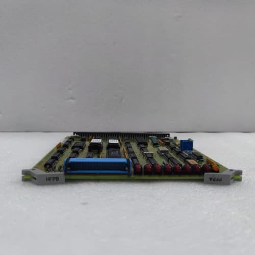
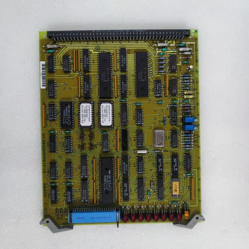
Description
Key Parameters
-
Digital Input Channels: 32 optically isolated (24V DC or 48V DC, jumper-selectable per bank)
-
Digital Output Channels: 32 solid-state or relay (24V DC, 0.5A per channel, depending on variant)
-
Input Voltage Range: 10–30V DC (for 24V setting) or 30–60V DC (for 48V setting)
-
Output Type: Open-collector transistor (sinking) with over-current protection
-
Isolation: 1500V RMS input-to-backplane, 1000V RMS output-to-backplane
-
Diagnostics: Per-channel LED status, input open-circuit detection, output short-circuit protection, fuse status
-
Response Time: <1ms for inputs, <2ms for outputs
-
Temp Range: –30°C to +70°C
-
Power Supply: +5V (logic), +24V (outputs) from backplane
-
Physical: 6U VME single-slot board
-
Key Features: 32 inputs + 32 outputs, bank-configurable voltage, per-channel diagnostics, high density
Advantages
-
High channel density – 64 total digital I/O points (32 in / 32 out) on a single board, replacing multiple lower-density digital boards and saving rack slots.
-
Bank configurability – inputs are grouped into banks of 8, each selectable for 24V or 48V operation, accommodating mixed field device voltages.
-
Optical isolation – inputs are fully isolated from the backplane, protecting the controller from field-side surges and noise.
-
Fast response – sub-millisecond input response and fast output switching for time-critical digital logic.
-
Visual diagnostics – per-channel LEDs provide instant status indication for troubleshooting.
-
Drop-in compatible – works with all Mark IV backplanes and processor configurations.
Applications
-
Turbine startup/shutdown sequencing – monitors permissives (lube oil pressure, hydraulic pressure, turning gear engagement) and drives start/stop commands.
-
Alarm and annunciation – receives alarm inputs from field devices and drives horn, beacon, and DCS alarm outputs.
-
Motor control – starts/stops auxiliary motors (cooling fans, pumps, oil mist eliminators) via digital outputs.
-
Valve position indication – monitors open/closed limit switches for isolation valves, drain valves, and bleed valves.
-
Interlock logic – provides discrete I/O for safety interlock circuits, such as fire detection, overspeed trip confirmation, and emergency stop pushbuttons.
vs Competitors & Related Variants
| Feature | DS3800XBFA | DS3800NVRC (Relay) | Generic VME Digital Board |
|---|---|---|---|
| Digital inputs | 32 | 0 (relay only) | 16–32 |
| Digital outputs | 32 (solid-state) | 16 (relay, 5A) | 16–32 (solid-state/relay) |
| Input voltage config | 24V/48V (bank) | N/A | Fixed or jumper |
| Output type | Open-collector | Form-C relay | Open-collector or relay |
| Response time | <1ms input / <2ms output | 10–15ms (relay) | 1–5ms |
| Isolation | 1500V input | 2500V (relay) | 500–1500V |
| Per-channel LED | Yes | Yes | Rarely |
| Output current | 0.5A | 5A | 0.5–2A |
| Temp range | –30°C to +70°C | –30°C to +70°C | 0°C to +60°C |
Key Differentiators:
-
The DS3800XBFA offers the highest digital I/O density among Mark IV boards, with 32 inputs and 32 outputs in a single slot.
-
It supports both 24V and 48V input devices, making it versatile for mixed-voltage plants.
-
Outputs are solid-state for fast, maintenance-free switching, unlike relay boards (e.g., DS3800NVRC) which have mechanical wear but handle higher currents.
-
For high-current loads (>0.5A), use an external interposing relay or the DS3800NVRC instead.
Selection Tips
-
High-density digital I/O needed – choose the DS3800XBFA when you need a large number of digital I/O points in a single slot, especially for turbine sequencing, alarm handling, or motor control.
-
Mixed input voltages – the bank-configurable 24V/48V inputs accommodate plants with both legacy 48V and modern 24V field devices.
-
Output current limitation – the General Electric DS3800XBFA outputs are rated at 0.5A. For solenoid valves or contactors requiring higher current, use interposing relays or the DS3800NVRC.
-
Fast response needed – solid-state outputs provide faster response than relay-based boards, making this suitable for time-critical interlock logic.
-
Spare strategy – keep one DS3800XBFA per 5–8 installed units; its high density makes it a critical component in I/O-heavy installations.
Critical Precautions
-
Input voltage selection – ensure the bank jumpers are set correctly for 24V or 48V before applying field power. Incorrect settings can damage input optocouplers on the DS3800XBFA.
-
Output over-current – do not exceed 0.5A per output channel. The DS3800XBFA has over-current protection, but sustained overloads can overheat and damage output transistors.
-
Inductive loads – for DC solenoid or relay coils connected to outputs, install a flyback diode across the load to prevent voltage spikes from damaging the General Electric DS3800XBFA output stages.
-
Wiring polarity – inputs are polarity-sensitive for 24V/48V DC. Observe correct wiring; reversed polarity may not cause immediate damage but can prevent correct sensing.
-
Grounding – use a common return (DC common) for field inputs and outputs connected to the DS3800XBFA to avoid floating grounds that can cause false readings.
-
Wiring separation – keep digital I/O wiring separate from AC power lines to prevent noise coupling into the DS3800XBFA.
-
Hot-swap – never insert or remove the DS3800XBFA while the rack is powered; this can cause bus errors or damage to the board.
-
ESD handling – always use a grounded wrist strap when handling the DS3800XBFA; CMOS logic components are ESD-sensitive.
-
Storage – store spare boards in anti-static bags in a dry, temperature-controlled environment to prevent connector corrosion.
A-B 1756-BA1
A-B 1756-BA2
A-B 1756-BA2


.jpg)
Reviews
There are no reviews yet.