
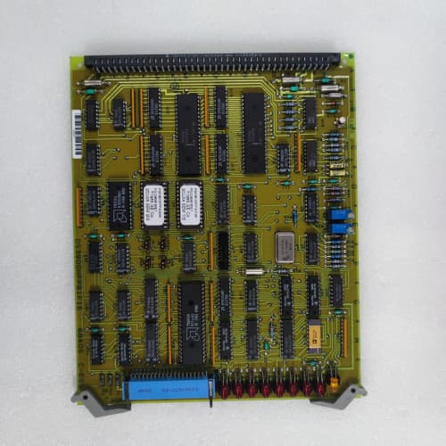
Description
Technical Parameters
| Parameter | Specification |
|---|---|
| Input Voltage | 125 VDC nominal (range 85–165 VDC); 24 VDC compatible with external adapter |
| Input Redundancy | Dual independent inputs with automatic failover (< 3ms) and jumper‑configurable priority |
| Output Rails | +24 VDC / 15A (field power), ±15 VDC / 3A (each rail, analog field circuits), +5 VDC / 5A (logic/communication) |
| Isolation | Full isolation (1.5kV input‑to‑output, 2.0kV output‑to‑ground) |
| Protection | Individual overcurrent protection per output (adjustable via jumpers), short‑circuit protection, transient suppression (6kV surge), reverse polarity protection, input undervoltage lockout |
| Regulation | Load regulation: ±0.15%; Line regulation: ±0.08%; Ripple: < 15mVpp (+24V), < 8mVpp (±15V), < 12mVpp (+5V) |
| Monitoring | 8 analog feedback channels (voltage and current monitoring for each output rail, plus input voltage and current monitoring); 6 digital fault outputs (relay, 24V/2A) for individual output faults, input failover, overtemp, load shed active, and system health |
| Digital Interface | 6 digital inputs for external enable/disable, status override, and load shedding control; 10 digital outputs for output status indication and external alarm signaling |
| Intelligent Control | Onboard dual‑core ARM Cortex‑M7 microcontroller for redundancy management, load sharing coordination, diagnostic reporting, predictive failure analytics (capacitor ESR, MOSFET health), event logging (10,000‑event buffer), and programmable load shedding |
| Load Shedding | Programmable load shedding with configurable priority levels for non‑critical outputs during input undervoltage conditions |
| Operating Temperature | –40°C to +70°C |
| Form Factor | 6U × 6HP (30mm) – requires 1.5 slots |
| Backplane Connector | Standard VME 96‑pin P1 + reinforced 60‑pin P2 (for second input and high‑current outputs) |
| Status LEDs | 12 indicators: INPUT 1 OK (green), INPUT 2 OK (green), +24V OK (green), +15V OK (green), –15V OK (green), +5V OK (green), FAULT (red), OVERTEMP (yellow), FAILOVER ACTIVE (amber), COMM ACTIVE (white), LOAD SHED ACTIVE (orange), PREDICTIVE ALERT (purple) |
| Certifications | CE, UL 508, CSA Class I Div 2, IEC 61508 SIL 2 (TÜV‑certified) |
| Efficiency | ~86% at full load |
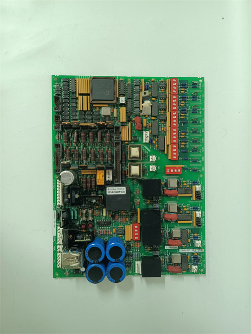
Critical note: The DS3800NRFA1F1E is a redundant field power interface designed for critical field device power distribution. It offers the highest capacity, advanced intelligent control, predictive analytics, event logging, and programmable load shedding in the NRFA family. This board is physically wider (6HP) than standard 4HP boards and requires 1.5 adjacent slots. Hot‑swapping is not supported.
Key Features & Advantages
-
Highest Capacity in NRFA Family – The DS3800NRFA1F1E offers the highest current ratings: +24V at 15A (25% more than 1E1D), ±15V at 3A (50% more), and +5V at 5A (25% more), making it suitable for the most demanding field device applications.
-
Advanced Intelligent Control – Onboard dual‑core ARM Cortex‑M7 microcontroller supports programmable load shedding, predictive failure analytics (capacitor ESR and MOSFET health monitoring), event logging (10,000 events), and diagnostic reporting via backplane communication.
-
Programmable Load Shedding – During input undervoltage conditions, the DS3800NRFA1F1E can shed non‑critical outputs based on configurable priority levels, preserving power for essential field devices.
-
Predictive Failure Analytics – The board continuously monitors capacitor ESR and MOSFET health, providing advanced warning (purple PREDICTIVE ALERT LED) before component failure occurs, enabling condition‑based maintenance.
-
Event Logging – The onboard 10,000‑event buffer stores power events (input transients, output deviations, load changes, temperature excursions, capacitor wear trends) with microsecond timestamps, enabling detailed failure analysis and predictive maintenance.
-
Comprehensive Monitoring – Eight analog feedback channels provide voltage and current telemetry for all output rails, plus input voltage and current monitoring, enabling detailed remote monitoring and load analysis.
-
Six Fault Relays – Six form‑C relay contacts (24V/2A) provide separate fault indication for each output rail, input failover, overtemp, load shed active, and system health.
-
Enhanced Digital I/O – Six digital inputs for external control and load shedding override; ten digital outputs for system status indication and external alarm signaling.
-
IEC 61508 SIL 2 Certification – TÜV‑certified for functional safety, making the DS3800NRFA1F1E suitable for safety‑related field power applications.
-
Wide Temperature Range – Extended –40°C to +70°C range makes the DS3800NRFA1F1E suitable for the most demanding environments.
Typical Application Cases
-
Critical Solenoid Valve Power – Provides redundant, conditioned power to safety shutdown solenoids, trip valves, and purge valves with programmable load shedding for priority devices.
-
Actuator Control Panels – Powers electric actuators for inlet guide vanes, bleed valves, and turbine bypass controls with individual overcurrent protection and predictive analytics for maintenance planning.
-
Field Transmitter Power – Supplies power to pressure transmitters, temperature sensors, and positioners in critical measurement loops requiring high availability and advanced diagnostics.
-
Redundant Field Device Cabinets – Installed in auxiliary panels where field device power continuity is essential for turbine operation.
-
Offshore Platforms with Dual Battery Banks – Dual input capability supports connection to two independent battery banks, ensuring power continuity during battery maintenance.
-
Upgrade from Lower NRFA Revisions – When an older NRFA board fails, the DS3800NRFA1F1E offers the ultimate performance upgrade without changing rack configuration.
Competitive Comparison
| Aspect | DS3800NRFA1F1E (GE) | DS3800NRFA1E1D (GE) | DS3800NPSL1A1A (GE) |
|---|---|---|---|
| Primary Output | +24V / 15A | +24V / 12A | 125VDC / 5A |
| Load Shedding | Programmable | No | No |
| Predictive Analytics | Yes | No | No |
| Event Logging | 10,000 events | No | No |
| Monitoring Channels | 8 (V + I) | 6 (V + I) | 1 (V only) |
| Fault Relays | 6 | 4 | 1 |
| Digital Inputs | 6 | 4 | 0 |
| Digital Outputs | 10 | 6 | 0 |
| SIL Certification | SIL 2 | None | None |
| Failover Time | < 3ms | < 5ms | N/A |
| Operating Temp | –40°C to +70°C | –30°C to +65°C | –25°C to +60°C |
| Price (refurb) | ~$6,800–$9,500 | ~$5,500–$7,800 | ~$2,800–$4,200 |
The DS3800NRFA1F1E is the flagship redundant field power interface in the DS3800 family, offering the highest capacity, most advanced intelligent control, predictive analytics, and SIL 2 certification.
Selection Guidelines & Precautions
-
Application Verification – The DS3800NRFA1F1E is designed for critical field device power distribution requiring maximum capacity, intelligent control, and predictive analytics. If your application does not require these advanced features, lower‑cost boards may be more appropriate.
-
Physical Compatibility – The DS3800NRFA1F1E is 6HP wide, requiring 1.5 adjacent slots in your Mark IV/V rack. It will not fit in standard 4HP slots.
-
Backplane Compatibility – Uses both P1 and reinforced P2 connectors. The second DC input, additional digital I/O, and backplane communication are provided through P2. If your backplane lacks P2, advanced features will be unavailable.
-
Input Priority Configuration – Configure primary/secondary priority via onboard jumpers (JP1‑JP2). The default uses Input 1 as primary and Input 2 as secondary.
-
Load Shedding Configuration – Program load shedding priority levels via backplane communication using GE Service Tool Software (version 5.0 or higher). Assign priority levels (1–4) to each output rail; lower‑priority outputs are shed first during undervoltage conditions.
-
Protection Threshold Adjustment – Configure overcurrent thresholds via onboard jumpers (JP3–JP6) based on field device requirements. Factory defaults are 120% of rated current.
-
Predictive Analytics – Access capacitor and MOSFET health data via backplane communication. The board estimates remaining lifetime and provides advanced warning when replacement is recommended (purple LED).
-
Event Log Retrieval – Access the event log via backplane communication or via the board’s dedicated Ethernet port (new in this revision). The log stores 10,000 events and can be exported in CSV format.
-
SIL 2 Compliance – For SIL 2 applications, follow GE safety manual GEI‑100912 for installation and configuration. Perform the required proof‑test intervals as specified.
-
Power Budget – Calculate total current draw:
-
+24V: max 15A
-
±15V: max 3A each
-
+5V: max 5A
Exceeding any output will trigger its individual overcurrent protection.
-
-
Grounding for Full Isolation – Use separate returns:
-
IN1_GND → Battery 1 negative
-
IN2_GND → Battery 2 negative
-
OUT_GND → Rack logic ground
Using a common ground defeats the isolation barrier and redundancy.
-
-
Thermal Derating – Full output available up to 60°C:
-
60°C–65°C: derate all outputs to 90% of rated current
-
65°C–70°C: derate all outputs to 80% of rated current
-
Above 70°C: do not operate
-
-
Spare Sourcing – Production ended in 2021. When purchasing refurbished units, request a comprehensive test report verifying all outputs at rated current, plus functional verification of load shedding, predictive analytics, event logging, input failover, and digital I/O at 25°C, 55°C, and 65°C. Verify SIL 2 compliance documentation if used in safety applications. Visually inspect for capacitor bulging, discoloration, or burned traces. The DS3800NRFA1F1E is the ultimate redundant field power solution—prioritize this for critical field device applications requiring maximum capacity, advanced intelligent control, predictive analytics, and SIL 2 certification.
FANUC A63L-0001-0234#S2524M
A-B 100-C16KF01
ABB 3HAC044075-001/01


Reviews
There are no reviews yet.