
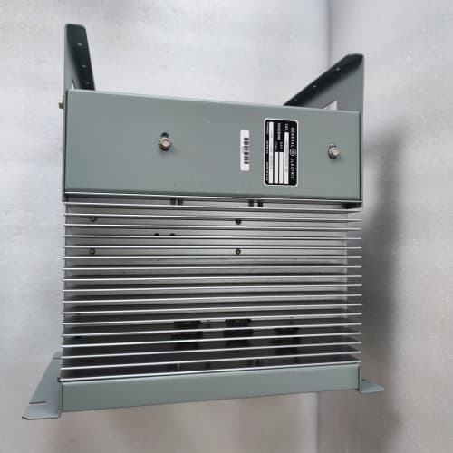
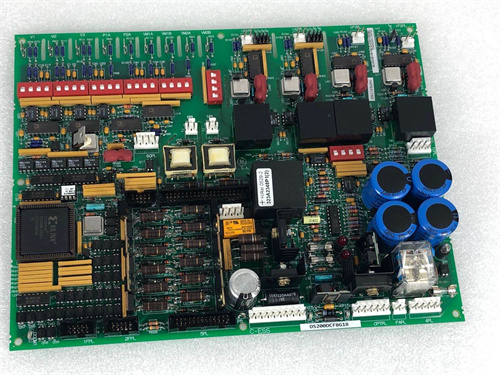
Description
Key Technical Parameters
| Parameter | Specification |
|---|---|
| Manufacturer | General Electric (GE) |
| Series | Mark V (Speedtronic) |
| Full Model | DS3800NFEE1G1H |
| Power Supply | +5V DC @ 4.5A, +15V DC @ 1.0A, -15V DC @ 0.6A (via backplane) |
| Temperature Inputs | 8 differential thermocouple channels (Type J/K/T, with 24-bit ADC) + 4 Pt100 RTD inputs |
| Output Configuration | Hybrid: 4 mechanical relays (8A @ 250VAC/30VDC) + 4 solid-state outputs (2A, 24–48VDC, PWM-capable) |
| Tachometer Inputs | 2 high-speed pulse channels (up to 15 kHz) for speed feedback on solid-state controlled fans |
| Communication | Mark V proprietary parallel backplane bus |
| Operating Temperature | -40°C to +75°C (military-grade components) |
| Storage Temperature | -55°C to +100°C |
| Vibration Resistance | 5g RMS, 10–500 Hz |
| LED Indicators | Power (green), Relay Run (4x amber), Solid-State Run (4x green), Over-Temp Alarm (red), Tach Fail (red), Adaptive Learning Active (blue), Bus Fault (red) |
Advantages and Distinctive Features
-
Hybrid Output Architecture: The DS3800NFEE1G1H uniquely combines 4 mechanical relays (for high-power exhaust fans up to 8A) and 4 solid-state outputs (for low-noise circulating fans with PWM speed control). This eliminates the need for two separate fan control boards in mixed-cabinet installations.
-
Adaptive Learning (Revision G): Upon first power-up, the DS3800NFEE1G1H performs a self-calibration routine that measures the inrush current and startup time of each connected fan. It then adjusts relay timing to minimize contact arcing and optimizes solid-state PWM ramp rates to reduce mechanical stress on fan bearings.
-
Dual Tachometer Feedback: Unlike other NFEE models, the DS3800NFEE1G1H includes 2 tachometer input channels for solid-state controlled fans. If a tach signal is lost, the board automatically switches the affected fan to a fixed 80% duty cycle and triggers a “Tach Fail” alarm—preventing complete airflow loss.
-
High-Precision Temperature Control: The 24-bit ADC provides ±0.5°C accuracy, enabling the DS3800NFEE1G1H to implement PID-based temperature regulation for solid-state outputs while maintaining simple on/off control for relay outputs.
-
Predictive Maintenance Alerts: The Revision G firmware tracks relay contact resistance and solid-state output leakage current. When degradation exceeds thresholds, the DS3800NFEE1G1H illuminates a yellow warning LED and stores an event in its 200-event fault log.
-
Self-Diagnostics: The board performs a complete power-on self-test (POST) every startup, verifying ADC linearity, relay coil integrity, and solid-state driver functionality. Failed tests trigger a red “Bus Fault” LED and prevent the DS3800NFEE1G1H from activating any outputs until cleared.
Typical Application Fields
-
Advanced Combined-Cycle Plants: Where cabinets contain both large exhaust blowers and small CPU cooling fans, the DS3800NFEE1G1H manages both with a single board.
-
Retrofit Upgrades: Replacing separate relay and solid-state boards with the DS3800NFEE1G1H reduces rack slot usage and simplifies wiring.
-
Offshore Platforms: The -40°C to +75°C range and 5g vibration tolerance make the DS3800NFEE1G1H suitable for harsh marine environments.
-
Data Center Turbine Backup Systems: Quiet, PWM-controlled solid-state outputs reduce acoustic noise in enclosed spaces while relay outputs handle backup cooling.
-
High-Altitude Installations: Adaptive learning compensates for reduced air density by adjusting PWM duty cycles to maintain specified airflow volume.
Comparison with Related Models
| Feature | DS3800NFEE1G1H | DS3800NFEE1E1E | DS3800NFEE1C1B | DS3800NFEC1B1B |
|---|---|---|---|---|
| Output Type | Hybrid (4 relay + 4 SS) | 8 relay (8A) | 8 relay (5A) | 8 solid-state (2A) |
| Max Relay Current | 8A (4 channels) | 8A (all 8) | 5A (all 8) | N/A |
| Solid-State PWM | Yes (4 channels) | No | No | Yes (8 channels) |
| Tachometer Inputs | 2 channels | None | None | 2 channels |
| Firmware Revision | G (adaptive learning) | E (predictive maint.) | C (enhanced CJC) | B (PID + tach) |
| Fault Log Capacity | 200 events | 100 events | Basic | 100 events |
| ADC Resolution | 24-bit (±0.5°C) | 24-bit (±0.5°C) | 16-bit (±1°C) | 16-bit (±1°C) |
| Operating Temp | -40°C to +75°C | -40°C to +75°C | -20°C to +65°C | -20°C to +65°C |
| Cost (Used) | Premium | Very High | Medium | High |
Selection Recommendations
-
Choose the DS3800NFEE1G1H if:
-
Your cabinet contains both high-power exhaust fans and low-power circulating fans.
-
You need PWM speed control for noise reduction or energy efficiency on some fans.
-
You want adaptive startup optimization to extend fan and relay life.
-
Predictive maintenance and comprehensive fault logging are required.
-
Your environment is extreme (-40°C to +75°C) with high vibration.
-
-
Choose the DS3800NFEE1E1E if: You need all 8 outputs as high-current relays (8A) without solid-state or PWM capability.
-
Choose the DS3800NFEC1B1B if: You need all 8 outputs as solid-state with PID and tachometer feedback, but can accept lower current (2A).
-
Choose the DS3800NFEE1C1B if: You need simple relay control (5A) without extreme temperature or advanced diagnostics.
Critical Precautions
-
ESD Protection: The DS3800NFEE1G1H contains sensitive 24-bit ADC and PWM driver circuits. Always wear a grounded ESD wrist strap and work on an ESD-safe mat.
-
Hybrid Output Wiring: Critical—Do not mix output types on the same connector terminal block. The 4 relay outputs (channels 1–4) are on the left side of the terminal strip; the 4 solid-state outputs (channels 5–8) are on the right side. Wiring a solid-state load (DC only) to a relay output is acceptable, but never wire an AC or high-current load to a solid-state output—this will permanently destroy the solid-state driver.
-
Solid-State Output Polarity: The solid-state outputs on the DS3800NFEE1G1H are DC-only (24–48VDC) and polarity-sensitive. Connect positive to the “SS Out +” terminal and negative/load to “SS Out -“. Reverse polarity will damage the internal MOSFET and void any warranty.
-
Tachometer Input Wiring: Use shielded twisted-pair cable for tachometer signals. Connect the shield to the DS3800NFEE1G1H‘s designated shield terminal (not at the fan end). Ground loops will cause false tach readings and may trigger unnecessary “Tach Fail” alarms.
-
Adaptive Learning Initialization: The first time you power up the DS3800NFEE1G1H with new fans, ensure all fans are in good working condition. The board will perform a 5-minute calibration cycle (flashing blue LED). Do not interrupt power during this phase—interruption will leave the board in an uncalibrated state, requiring a factory reset via the Mark V diagnostic menu.
-
No Hot-Swap: Always depower the Mark V rack before inserting or removing the DS3800NFEE1G1H. Backplane connectors are not rated for live insertion/removal.
-
Slot Assignment: Install the DS3800NFEE1G1H in auxiliary I/O slots (typically slots 8–10). Do not install in CPU or analog input slots—the hybrid outputs can inject switching noise into sensitive circuits.
-
Firmware Compatibility: The Revision G firmware on the DS3800NFEE1G1H requires Mark V CPU firmware v5.5 or higher. If your CPU runs older firmware, the adaptive learning and predictive maintenance features will be disabled. Contact GE for a CPU upgrade if needed.
-
Regular Relay Maintenance: Even with adaptive learning, mechanical relay contacts on the DS3800NFEE1G1H have a finite lifespan (approx. 150,000 operations at 8A). Monitor the blue “Adaptive Learning Active” LED—if it remains on continuously (indicating the board is overcompensating for worn contacts), schedule a replacement for the affected relay channels. Individual relays on the DS3800NFEE1G1H are not field-replaceable; the entire board must be replaced.
SIEMENS 6GK 1500-OEA02
HR-WP-XD423-011-22/22-HL/HL-P-W

.jpg)

Reviews
There are no reviews yet.