
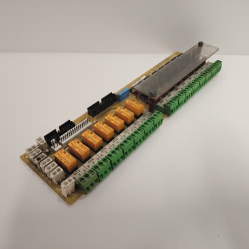
Description
Technical Parameters
-
Product Type: Processor / regulator interface board
-
Processor interface: 32-bit parallel data bus to main regulator (531X111 series)
-
Timing generation: 12.5 µs PWM cycle (80 kHz) with ±0.1% accuracy
-
Gate drive outputs: 6 isolated firing pulses to power modules (via 531X144 gate driver)
-
Fault detection: Overcurrent, overvoltage, ground fault, and desaturation inputs
-
Analog feedback: 4 channels (motor current, DC bus voltage, temperature, etc.)
-
Communications: Dedicated serial link to operator keypad and PC tool
-
Fault logging: 16-event history buffer with time stamps
-
Isolation: 1500 Vrms between logic and power sections
-
Connectors: Two 26-pin headers (to regulator and gate driver); one 10-pin keypad connector
-
Mounting: 4× M4 holes (standard GE rack footprint)
-
Power supply: +5 VDC and ±15 VDC from 531X146 power supply
-
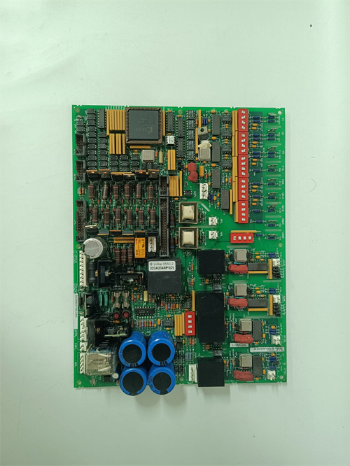
LED indicators: Power, Fault, Run, and 6 gate status LEDs
Advantages & Features
-
High-speed timing – 80 kHz PWM cycle with ±0.1% accuracy ensures smooth motor torque and low audible noise
-
Comprehensive fault detection – Monitors overcurrent, overvoltage, ground fault, and IGBT desaturation on GE 531X161PRTABG1, providing complete protection for the drive system
-
Fault logging – 16-event history buffer with time stamps simplifies troubleshooting of intermittent faults
-
Direct interface – Bridges the regulator board, gate driver, and keypad in a single board, reducing interconnect complexity
-
Enhanced diagnostics – 6 individual gate status LEDs indicate firing status for each phase, speeding up commissioning
-
Plug-and-play – Direct replacement for earlier PRT revisions; no parameter changes required
Application Cases
-
Commissioning support – System integrator used gate status LEDs on GE 531X161PRTABG1 to verify proper IGBT firing sequence during AC-300 drive startup, reducing commissioning time by 40%
-
Fault analysis – Paper mill drive experienced intermittent overcurrent trips; the fault log on GE 531X161PRTABG1 identified a recurring desaturation fault on phase C, leading to replacement of a faulty IGBT module
-
Retrofit – Replaced failed PRT board in 500 HP DC-300 drive with GE 531X161PRTABG1, restoring operation within 2 hours without retuning the drive
Competitive Comparison
| Aspect | GE 531X161PRTABG1 (OEM) | Generic Replacement Processor Board |
|---|---|---|
| Timing accuracy | ±0.1% (80 kHz) | ±1% typical (lower PWM frequency) |
| Fault logging | 16-event buffer with time stamps | None or limited |
| Gate status LEDs | 6 individual (per phase) | Limited or none |
| Desaturation detection | Yes (hardwired fast response) | May rely on software (slower) |
| Interface compatibility | Direct plug-in to GE regulator | Requires adapter or rewiring |
| Cost | Higher upfront, lower TCO | Cheaper but untested compatibility |
Selection Suggestions
-
Verify your regulator board type – GE 531X161PRTABG1 works with 531X111 series regulator boards (check revision compatibility)
-
Confirm gate driver board compatibility – works with 531X144DRGAAG1 and similar DRG series
-
For systems with intermittent faults, the fault logging feature on GE 531X161PRTABG1 is invaluable for diagnostics
-
Prefer remanufactured units with new timing crystals and capacitors – aged crystals affect timing accuracy
-
If replacing a failed board, check the IGBT modules for shorts before installation – a downstream short will destroy the new PRT board
Precautions
-
Always disconnect power before handling GE 531X161PRTABG1 – high voltages present on gate cables and power connections
-
Do not operate the board without all gate cables connected – unloaded gate drivers can oscillate and damage the PRT board
-
When replacing, transfer all parameter settings from the old GE 531X161PRTABG1 to the new board – this includes fault limits and timing parameters
-
Check all connections before power-up – incorrect wiring between PRT and gate driver can cause IGBT shoot-through
-
Use anti-static handling – the processor interface ICs are ESD-sensitive
-
Torque mounting screws to 2–3 N·m – over-tightening cracks the PCB
-
If the “Fault” LED is illuminated, check the fault history log first – this will indicate the specific fault cause, saving hours of troubleshooting
-
Do not hot-swap cables – connecting or disconnecting while powered will damage the GE 531X161PRTABG1
-
The board must be mounted with proper spacing for airflow – inadequate cooling affects crystal oscillator stability
YASKAWA SGMAH-04AAA61D-OY
A-B 1746-NI8
A-B 1746-NI4
A-B 1756-CNB/E


Reviews
There are no reviews yet.