
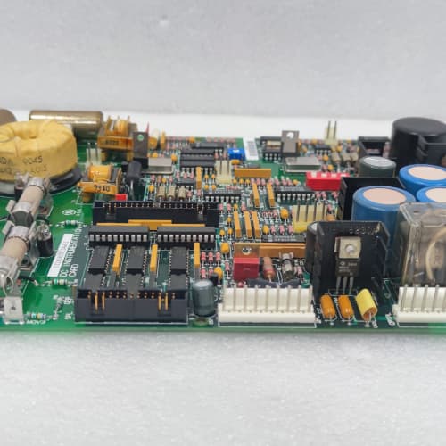
Description
Technical Parameters
-
Product Type: Terminal board / field wiring termination assembly
-
Digital I/O terminals: 16 screw-type + 16 spring-clamp (mixed) – 32 total points – with integral LED status indicators (green = ON)
-
Analog I/O terminals: 12 points (voltage/current) – with TVS surge protection
-
Communication terminals: 6 points (RS-485, RS-232) – with ESD protection
-
Auxiliary power terminals: 6 points (120 VAC / 24 VDC) – screw-type only
-
Terminal types: Screw (0.2–2.5 mm² / 24–12 AWG) and Spring-clamp (0.2–1.5 mm² / 24–16 AWG)
-
Current rating: Screw: 10 A; Spring-clamp: 8 A
-
Voltage rating: 300 VAC / 600 VAC (terminal-to-terminal)
-
LED indicators: 32 individual status LEDs (one per digital I/O point)
-
Labeling: Color-coded signal groups (digital = blue, analog = green, power = red, comms = yellow)
-
Surge protection: TVS diodes on analog and communication terminals (±2 kV)
-
Conformal coating: Marine-grade (moisture and corrosion resistant) – AGG1 specific
-
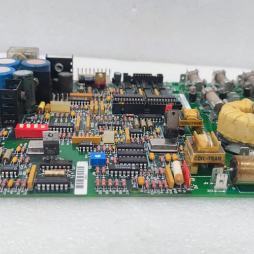
Connectors: Two 34-pin headers to regulator board; one 26-pin header to auxiliary boards
-
Mounting: 4× M4 holes (standard GE rack footprint)
-
Operating temperature: -20°C to 70°C (extended range)
Advantages & Features
-
Hybrid terminal design – Mix of screw and spring-clamp terminals on GE 531X170TBSAGG1 provides flexibility: screw terminals for field instruments requiring high-retention or heavy wire; spring-clamp for rapid installation of smaller gauge wiring
-
Integral LED status indicators – 32 individual LEDs (green = ON) provide immediate visual confirmation of digital I/O status, eliminating the need for a multimeter during troubleshooting
-
Color-coded labeling – Signal groups are color-coded on GE 531X170TBSAGG1 (digital/blue, analog/green, power/red, comms/yellow) for rapid identification and reduced wiring errors
-
Marine-grade conformal coating – Protects GE 531X170TBSAGG1 from humidity, salt spray, and corrosive gases, making it suitable for offshore, marine, and chemical plant environments
-
Extended temperature range – -20°C to 70°C for unheated enclosures or high-ambient environments
-
Built-in surge protection – TVS diodes protect analog and communication terminals from voltage spikes
-
Plug-and-play – Direct replacement for earlier TBS revisions; no configuration changes needed
Application Cases
-
Offshore platform – AC-300 drive exposed to salt spray and wide temperature swings (-10°C to 65°C) used GE 531X170TBSAGG1; hybrid terminals accommodated both legacy screw-terminated sensors and new push-in instruments; conformal coating prevented corrosion
-
Rapid commissioning with mixed wiring – Chemical plant with mixed field wiring used GE 531X170TBSAGG1; screw terminals for older instruments, spring-clamp for new devices; integral LEDs and color-coded labeling reduced commissioning time by 40%
-
Cold storage + high humidity – Food processing plant with unheated storage areas (-15°C) and washdown areas used GE 531X170TBSAGG1; extended temperature range and conformal coating ensured reliable operation in both freezing and high-humidity conditions
Competitive Comparison
| Aspect | GE 531X170TBSAGG1 (OEM) | Generic Replacement Terminal Board |
|---|---|---|
| Terminal types | Hybrid (screw + spring-clamp) | One type only (screw or spring) |
| LED indicators | 32 integral (status per point) | None |
| Labeling | Color-coded signal groups | Basic or unlabeled |
| Temperature range | -20°C to 70°C | 0°C to 50°C typical |
| Conformal coating | Marine-grade (moisture/corrosion) | None or basic |
| Corrosion resistance | High (salt spray, chemicals) | Low to moderate |
Selection Suggestions
-
Choose GE 531X170TBSAGG1 for offshore, marine, chemical, or high‑humidity installations with mixed field wiring – conformal coating, hybrid terminals, and LEDs provide maximum flexibility and reliability
-
Select AGG1 if your installation has mixed wiring types (some screw-terminated, some push-in) – the hybrid design eliminates the need for separate terminal blocks
-
For troubleshooting convenience, integral LEDs on GE 531X170TBSAGG1 are a significant advantage – rapid status verification without test equipment
-
Verify your field wiring is within accepted ranges: screw terminals accept 24–12 AWG; spring-clamp accept 24–16 AWG – GE 531X170TBSAGG1 covers most applications
-
Confirm regulator board compatibility – works with 531X111, 531X139, and 531X305 series
-
Prefer remanufactured units with all terminals tested, LED function verified, and conformal coating intact – any damage to the coating reduces corrosion protection
Precautions
-
Always disconnect power before handling GE 531X170TBSAGG1 – field wiring may carry high AC voltages
-
Do not exceed terminal current ratings: 10 A (screw) or 8 A (spring) – higher current damages the terminal block and PCB traces
-
Verify wire insulation rating meets 300 VAC minimum – underrated insulation may arc between terminals
-
For stranded wires on spring-clamp terminals, use ferrules to prevent strand fraying – exposed strands can short adjacent terminals on GE 531X170TBSAGG1
-
Do not mix screw and spring-clamp wiring for the same signal group without verifying common reference – the hybrid design may create unintentional ground loops
-
When replacing, label all field wiring before removing the old board – color-coded labeling on GE 531X170TBSAGG1 helps identify groups, but individual marking is still recommended
-
Maintain separation between high-voltage and low-voltage wiring – 8 mm creepage distance must be observed
-
The integral LEDs on GE 531X170TBSAGG1 indicate signal presence only – they do not test signal quality (voltage level, noise, or current)
-
Conformal coating protects the PCB but not the terminal screws – use corrosion‑resistant wire (tinned copper) to prevent galvanic corrosion at the terminal interface
-
For analog signals, use shielded cables and ground the shield at the drive end only – reduces EMI-induced errors
-
Torque screw terminals to 0.5–0.6 N·m – over-tightening strips threads; under-tightening causes loose connections and overheating
-
Insert spring-clamp wires fully until the wire stop is reached – partially inserted wires cause intermittent connections
-
Inspect conformal coating for scratches or cracks before installation – damaged coating exposes the PCB to corrosion and voids the protective feature of GE 531X170TBSAGG1
A-B 1794-IF2X0F2I
п XP316
A-B 440R-C23017

Reviews
There are no reviews yet.