
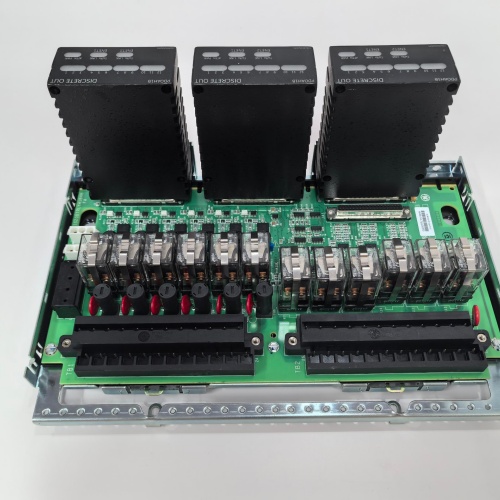
Description
Key Specifications
| Parameter | Specification |
|---|---|
| Thermocouple Input Channels | 8 dual-TC channels (16 total thermocouple inputs) |
| Thermocouple Types Supported | J, K, T, E, N, R, S, B — software-selectable |
| Thermocouple Accuracy | ±0.1% of reading + ±0.5 °C (typical) |
| Cold Junction Compensation | Integrated CJC sensors (±0.25 °C accuracy) |
| Current Input Channels | 4 differential analog inputs (4–20 mA, loop-powered) |
| Current Input Resolution | 16-bit ADC |
| Current Input Accuracy | ±0.05% of full scale |
| Current Input Load | 250 Ω (typical) |
| Dual-Sensor Redundancy | Each thermocouple channel supports two independent sensors |
| Redundancy Logic | On-board average, difference, maximum, and minimum calculation |
| Burnout Detection | Open-circuit detection for thermocouple faults |
| Isolation | 1500 VDC (I/O-to-backplane) |
| Diagnostics | 500-event fault log with timestamps |
| Sample Rate | 10 Hz (sequential scanning) |
| Communication | I/O Net (dual Ethernet ports for redundancy) |
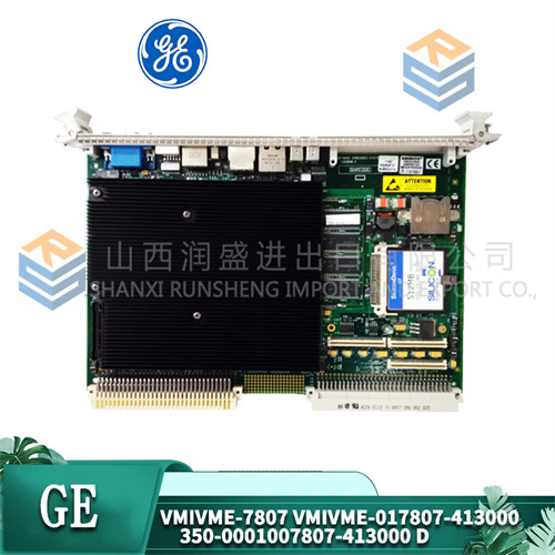
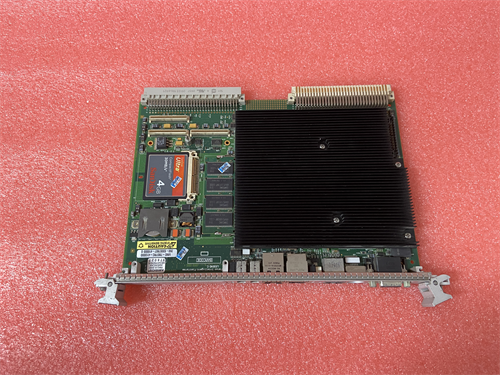
| Form Factor | 6U VME64x (160 × 233 mm), single-slot width |
| Indicators | Per-channel LED, module health, communication status |
| Operating Temp | 0 °C to +60 °C |
| Power Draw | 12 W (+5 V / +3.3 VDC) |
| Connectors | Front-panel 48-pin terminal block with gold-plated contacts and captive washer screws |
Advantages & Distinctive Features
-
Dual-Thermocouple Redundancy: Each channel supports two independent thermocouples for redundant temperature measurement.
-
On-Board Redundancy Logic: Average, difference, maximum, and minimum calculations—reduces processor load.
-
Integrated Current Inputs: 4 dedicated 4–20 mA inputs for pressure, flow, or position transmitters.
-
Integrated Cold Junction Compensation: Dedicated CJC sensors for accurate absolute temperature readings.
-
Burnout Detection: Open-circuit detection for thermocouple faults.
-
Loop-Powered Support: 4–20 mA inputs support loop-powered transmitters (no external power required).
-
High Accuracy: ±0.1% reading + ±0.5 °C for thermocouples; ±0.05% for current inputs.
-
Gold-Plated Captive Washer Terminals: Corrosion-resistant and vibration-proof.
-
Hot-Swappable: No rack power-down for replacement.
-
Direct Retrofit: Replaces older DTCI series boards.
Application Fields
-
Gas Turbines: Exhaust temperature (dual TC), pressure transmitters (4–20 mA)
-
Steam Turbines: Casing temperature (dual TC), pressure transmitters
-
Compressors: Inlet/discharge temperature (dual TC), pressure transmitters
-
Generators: Stator winding temperature, pressure monitoring
-
Critical Temperature Monitoring: Applications requiring redundant TC sensors for safety
Comparison with DTAIH1A and Competitors
| Feature | GE IS210DTCIH1A | GE IS210DTAIH1A | Competitor A | Competitor B |
|---|---|---|---|---|
| TC Channels | 8 (dual) / 16 inputs | 8 (dual) / 16 inputs | 8 (single) | 8 (dual) |
| Current Inputs | 4 (4–20 mA) | None | None | 4 |
| Voltage Inputs | None | 4 | None | None |
| Redundancy Logic | Average/Diff/Max/Min | Average/Diff/Max/Min | No | No |
| Hot-Swappable | Yes | Yes | No | Yes |
Selection Guidelines
-
When to choose: Applications requiring redundant TC monitoring with 4–20 mA transmitter inputs.
-
When to choose DTAIH1A instead: Applications requiring voltage inputs (0–10 V, ±10 V) instead of current inputs.
-
Redundancy Logic: Configure average for normal operation; difference for fault detection.
-
TC Configuration: Configure per channel for thermocouple type in Toolbox ST.
-
Current Configuration: Configure 4–20 mA range and scaling in Toolbox ST.
-
Compatibility: Fits all Mark VIe VME64x racks. Requires ControlST v6.0 or higher.
Operational Precautions
-
Wiring: Follow GE wiring diagrams—correct polarity and shield grounding essential.
-
Dual-TC Wiring: Ensure both thermocouples are correctly wired per channel.
-
Current Input Wiring: Ensure correct polarity for 4–20 mA loop connections.
-
Redundancy Logic Testing: Simulate one TC failure to verify redundancy logic.
-
Calibration: Factory calibrated—verify against known references during commissioning.
-
LED Diagnostics: Green = normal; Amber = sensor fault/difference; Red = module fault.
-
Fault Log: Access 500-event log via Toolbox ST.
-
Hot-Swap: Remove/insert slowly under power.
-
Spare Stock: Maintain 1 spare per 3–4 racks.
-
ESD: Handle by edges with grounded wrist strap.
A-B 140A-C2A-B16
SIEMENS 6ES5318-8MB13
A-B 150-C37NBR

Reviews
There are no reviews yet.