
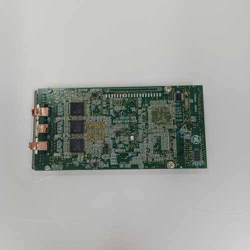
Description
Key Specifications
| Parameter | Specification |
|---|---|
| Control Loops | 2 independent PID/servo loops (primary governor + secondary/auxiliary) |
| Speed Inputs | 2 independent speed channels (magnetic pickup or proximity probe) |
| Speed Range | 0 to 60,000 RPM |
| Speed Accuracy | ±0.005% of reading |
| Analog Inputs | 6 configurable (4–20 mA, 0–10 V, ±10 V) for load feedback, pressure, temperature |
| Analog Outputs | 4 configurable (4–20 mA, 0–10 V) for fuel valve, IGV actuator control |
| Discrete Inputs | 8 configurable (24 VDC) for trips, status signals |
| Discrete Outputs | 8 configurable (24 VDC, 0.5 A) for trips, alarms, solenoid control |
| Control Algorithms | PID, cascaded PID, feedforward, rate-limiting, valve position feedback |
| Response Time | <20 ms for speed loop (3-batch update) |
| Communication | I/O Net (dual Ethernet ports for redundancy) |
| Form Factor | 6U VME64x (160 × 233 mm), single-slot width |
| Indicators | Module health, communication status, per-channel status LEDs |
| Operating Temp | 0 °C to +60 °C |
| Power Draw | 15 W (+5 V / +3.3 VDC) |
| Diagnostics | Non-volatile fault logging — stores last 500 events with timestamps |
Advantages & Distinctive Features
-
Integrated Governor Control: Combines speed detection, PID control, and actuator outputs in a single module—reduces rack space and simplifies wiring compared to external governor systems.
-
Dual Control Loops: Supports primary governor (speed/load) and secondary control (pressure, temperature, or acceleration limiting) for comprehensive turbine control.
-
High Speed Accuracy: ±0.005% speed reading ensures precise governor response and stable grid synchronization.
-
Flexible I/O: Mix of analog and discrete I/O accommodates various feedback sources and actuator types without additional modules.
-
Fast Response: <20 ms speed loop response meets grid code requirements for frequency regulation.
-
Built-in Control Algorithms: Pre-engineered PID, feedforward, and rate-limiting functions reduce engineering effort—configured in Toolbox ST.
-
Valve Position Feedback: Supports LVDT/RVDT or potentiometer feedback for closed-loop valve position control.
-
Hot-Swappable: Supports removal and replacement without powering down the rack.
-
Direct Retrofit: Replaces older VTURG H1A series boards.
Application Fields
-
Gas Turbines: Speed governor control, load control, fuel/air ratio control, inlet guide vane (IGV) control
-
Steam Turbines: Speed governor, pressure control, extraction control, bypass valve positioning
-
Combined Cycle: Plant-level load coordination between gas and steam turbines
-
Grid-Synchronous Operation: Frequency regulation and droop control
-
Marine Propulsion: Main engine governor control
-
Compressors: Speed control for variable-speed drives
Comparison with Competitors
| Feature | GE IS200VTURG1B | Competitor A (Woodward 505) | Competitor B (Siemens T-3000) |
|---|---|---|---|
| Control Loops | 2 | 1 | 1 |
| Speed Inputs | 2 (redundant) | 1 | 1 |
| Speed Accuracy | ±0.005% | ±0.01% | ±0.01% |
| Response Time | <20 ms | <30 ms | <25 ms |
| Analog I/O | 6 AI / 4 AO | 4 AI / 2 AO | 4 AI / 2 AO |
| Discrete I/O | 8 DI / 8 DO | 4 DI / 4 DO | 4 DI / 4 DO |
| Control Algorithms | PID, cascade, feedforward, rate-limiting | PID | PID |
| Hot-Swappable | Yes | No | No |
The GE IS200VTURG1B offers superior I/O density, dual-loop capability, and faster response than competitors—making it the ideal solution for turbine governor control in a single VME slot.
Selection Guidelines
-
When to choose: Any Mark VIe application requiring speed governor control—gas turbines, steam turbines, or variable-speed compressors.
-
Speed Sensor Selection: Use magnetic pickups (500 mV–100 V) or proximity probes (5–24 VDC). Verify sensor cable length meets specifications.
-
Control Loop Configuration: Configure primary loop for speed/load control; secondary loop for pressure, temperature, or acceleration limiting.
-
Valve Feedback: Connect LVDT/RVDT or potentiometer feedback to analog inputs for position feedback—critical for accurate valve positioning.
-
PID Tuning: Start with default PID parameters in Toolbox ST, then fine-tune based on observed step response. Use rate-limiting to prevent mechanical stress.
-
Compatibility: Fits all Mark VIe VME64x racks. Requires processor board (VPRO series) with I/O Net connectivity and ControlST v6.0 or higher.
Operational Precautions
-
Wiring: Follow GE wiring diagrams (GEH-6850)—correct polarity and shield grounding essential for speed sensors and analog signals.
-
Speed Calibration: Verify speed readings against a known reference (portable tachometer) during commissioning—critical for governor accuracy.
-
PID Tuning: Perform step tests during commissioning—adjust gains gradually to avoid overshoot or instability. Document final settings.
-
Valve Stroke Test: Perform a full-stroke valve test to verify valve position feedback and actuator response before placing the turbine in service.
-
Droop Configuration: Set droop per grid code requirements (typically 3–5%) for parallel operation.
-
LED Diagnostics: Green = normal, Amber = marginal/fault, Red = trip condition. Refer to GEH-6850 for blink codes.
-
Fault Log: Access 500-event log via Toolbox ST for post-event analysis.
-
Hot-Swap Procedure: When replacing a GE IS200VTURG1B under power, remove and insert slowly to avoid inrush spikes.
-
Spare Stock: Maintain at least one spare GE IS200VTURG1B per 3–4 active racks—critical for turbine availability.
-
Annual Verification: Perform speed and load control tests during outages—verify response times and compare with baseline data.
-
Firmware Updates: Ensure the GE IS200VTURG1B is in “standby” mode during updates.
-
ESD Handling: Handle by edges only using grounded wrist straps and ESD-safe workstations.
A-B 1756-PA72 C
Mitsubishi FCUA-DX110
SCHNEIDER TWDLCAA24DRF
MOXA CP-118U-1



Reviews
There are no reviews yet.