
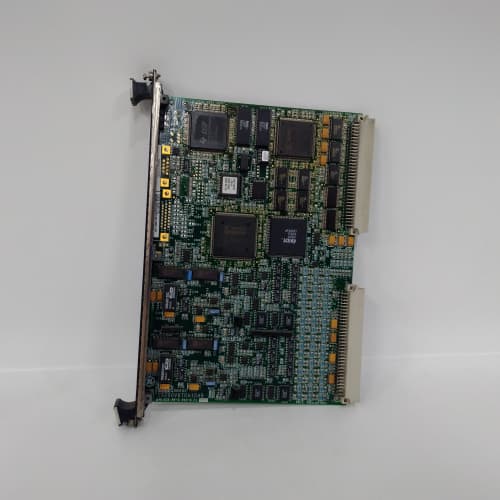
Description
Key Specifications
| Parameter | Specification |
|---|---|
| Input Channels | 24 differential thermocouple inputs |
| Thermocouple Types Supported | J, K, T, E, N, R, S, B, C (software-selectable per channel) |
| Input Signal Range | –20 mV to +100 mV (millivolt range) |
| Accuracy | ±0.1% of reading + ±0.5 °C (typical, including cold junction compensation) |
| Cold Junction Compensation (CJC) | Integrated with dedicated CJC temperature sensors per bank (accuracy ±0.25 °C) |
| Resolution | 24-bit ADC |
| Sample Rate | 10 Hz (100 ms per channel, sequential scanning) |
| Input Protection | Overvoltage protection (±35 VDC continuous), ESD protection (IEC 61000-4-2 Level 4) |
| Input Filtering | Programmable digital filtering (4 levels) |
| Isolation | 1500 VDC (channel-to-backplane) |
| Communication | I/O Net (dual Ethernet ports for redundancy) |
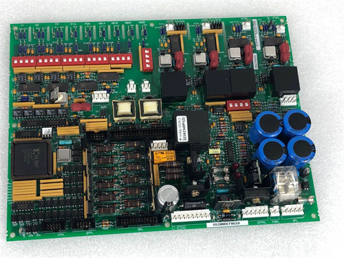
| Form Factor | 6U VME64x (160 × 233 mm), single-slot width |
| Indicators | LED for each channel (signal OK / fault), module health, communication status |
| Operating Temp | 0 °C to +60 °C |
| Power Draw | 12 W typical (+5 V / +3.3 VDC) |
| Connectors | Front-panel 48-pin terminal block (screw-type) with gold-plated contacts |
| Diagnostic Memory | Non-volatile fault logging — stores last 500 events with timestamps |
| Built-in Test | Open/short circuit detection, burnout detection (up/down scale selectable), CJC sensor health monitoring |
Advantages & Distinctive Features
-
High Channel Density: 24 thermocouple inputs per module—reduces rack space and cost per channel.
-
Wide Thermocouple Support: Supports J, K, T, E, N, R, S, B, and C types—accommodates all common turbine temperature measurement applications.
-
Integrated Cold Junction Compensation: Dedicated CJC sensors with ±0.25 °C accuracy ensure accurate absolute temperature readings without external reference junctions.
-
High Accuracy: ±0.1% reading + ±0.5 °C ensures reliable temperature measurements for critical turbine protection (exhaust gas temperature, combustion monitoring).
-
Burnout Detection: Selectable up-scale or down-scale output on sensor failure—ensures failsafe operation (critical for turbine protection logic).
-
Programmable Filtering: 4-level digital filtering reduces noise from electrically noisy environments (near VFDs, high-power cables).
-
Gold-Plated Connectors: Corrosion-resistant terminals ensure reliable connections in high-humidity environments.
-
I/O Net Integration: Seamless communication with processor boards via redundant Ethernet links.
-
Hot-Swappable: Supports removal and replacement without powering down the rack.
-
Direct Retrofit: Replaces VTCC H1A series boards with enhanced capabilities.
Application Fields
-
Gas Turbines: Exhaust gas temperature monitoring (EGT), combustion monitoring, turbine inlet temperature
-
Steam Turbines: Casing temperature monitoring, bearing temperature (thermocouple type)
-
Generators: Stator winding temperature monitoring (thermocouple type)
-
Compressors: Inlet/discharge temperature monitoring
-
Heat Recovery Steam Generator (HRSG) : Superheater and reheater outlet temperature monitoring
-
Industrial Furnaces: Process temperature monitoring
-
Research & Development: Test cell temperature measurements
Comparison with Competing Products
| Feature | GE IS200VTCCH1B | Competitor A (Siemens ET200SP TC) | Competitor B (Rockwell 1794-IT8) |
|---|---|---|---|
| Channels | 24 | 8 | 8 |
| Thermocouple Types | J, K, T, E, N, R, S, B, C | J, K, T, E, N, R, S | J, K, T, E, R, S |
| CJC Accuracy | ±0.25 °C | ±0.5 °C | ±0.5 °C |
| Accuracy | ±0.1% + ±0.5 °C | ±0.2% + ±1 °C | ±0.15% + ±1 °C |
| Burnout Detection | Selectable up/down scale | Fixed up-scale | Fixed down-scale |
| Digital Filtering | 4-level programmable | Basic | Basic |
| Isolation | 1500 VDC | None | 500 VDC |
| Fault Logging | 500 events | No | No |
| Hot-Swappable | Yes | Yes | Yes |
The GE IS200VTCCH1B offers superior channel density, wider thermocouple support, better accuracy, and more diagnostics than competitors—making it the ideal solution for comprehensive turbine temperature monitoring.
Selection Guidelines
-
When to choose: Any Mark VIe application requiring thermocouple temperature measurement—gas turbines, steam turbines, compressors, HRSG systems.
-
Thermocouple Selection: Verify field thermocouple type and configure per channel in Toolbox ST. Use appropriate extension wire (e.g., type K extension wire for K thermocouples) to avoid cold junction errors.
-
CJC Consideration: The GE IS200VTCCH1B has integrated CJC sensors located near the terminal block. Ensure terminal block temperature is stable—avoid mounting near heat sources or in direct airflow.
-
Burnout Configuration: Select up-scale for most turbine protection applications (sensor failure reads high → protection logic may trip as failsafe) or down-scale for applications where low reading is safer.
-
Filtering Configuration: Program filtering per channel based on noise levels. For gas turbine exhaust monitoring (noisy environment), use Level 3 or 4 filtering; for clean environments, Level 1 or 2 for faster response.
-
Wiring: Use shielded twisted-pair thermocouple extension wire. Connect shield to the terminal block ground only (single-point grounding) to avoid ground loops.
-
Compatibility: Fits all Mark VIe VME64x racks. Requires processor board (VPRO series) with I/O Net connectivity and ControlST v6.0 or higher.
Operational Precautions
-
Wiring: Follow GE wiring diagrams (GEH-6830)—correct polarity essential (thermocouples are polarized). Use thermocouple-grade extension wire (not copper wire). Shield ground at terminal board only.
-
Cold Junction Compensation: Ensure terminal block is at stable ambient temperature—avoid mounting near heat sources or in direct airflow. The module uses CJC sensors per bank—if CJC sensor fails, the channel will report a fault.
-
Burnout Testing: Simulate an open-circuit condition (disconnect thermocouple wire) to verify burnout detection and output direction (up/down scale) during commissioning.
-
Calibration: Factory calibrated—no field calibration required. However, verify temperature readings against a known reference (e.g., millivolt calibrator) during commissioning for critical protection channels.
-
Diagnostic Interpretation: Channel LED codes: Green = normal; Amber = out-of-range (temperature outside configured limits) or CJC fault; Red = burnout/open circuit. Refer to GEH-6830 for blink code details.
-
Fault Log: Access 500-event log via Toolbox ST for post-event analysis.
-
Filtering Tuning: Start with Level 2 (standard) and adjust based on observed noise. Increasing filtering reduces noise but increases response time (200 ms for Level 4).
-
Hot-Swap Procedure: When replacing a GE IS200VTCCH1B under power, remove and insert slowly to avoid inrush spikes. The processor board automatically recognizes the new module.
-
Spare Stock: Maintain at least one spare GE IS200VTCCH1B per 3–4 active racks.
-
Annual Verification: Verify each channel against a known temperature reference (millivolt calibrator) during scheduled outages. Document drift trends.
-
Firmware Updates: Ensure the GE IS200VTCCH1B is in “standby” mode during updates. Use ControlST v6.0 or higher.
-
ESD Handling: Handle by edges only using grounded wrist straps and ESD-safe workstations.
SCHNEIDER 140CRP93100
BENTLY 330180-50-00
SIEMENS 6ES7331-1KF02-0AB0
AB 1756-IF16


Reviews
There are no reviews yet.