
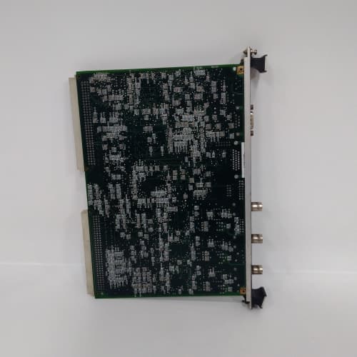
Description
Key Specifications
| Parameter | Specification |
|---|---|
| Speed Input Channels | 3 independent channels (redundant configuration) |
| Sensor Types Supported | Magnetic pickups, proximity probes (eddy current), tachometers (TTL/CMOS) |
| Input Signal Range | 100 mV to 100 V peak-to-peak (magnetic pickup); 5–24 VDC (proximity/tachometer) |
| Frequency Range | 0.5 Hz to 25 kHz |
| Speed Measurement Range | 0 to 60,000 RPM (programmable scaling) |
| Accuracy | ±0.01% of reading |
| Protection Functions | Overspeed trip (3 redundant channels, 2-out-of-3 voting logic), under-speed detection, zero-speed detection, speed rate-of-change monitoring |
| Response Time | <5 ms for overspeed trip detection |
| Isolation | 1500 VDC (channel-to-backplane) |
| Communication | I/O Net (dual Ethernet ports for redundancy) |
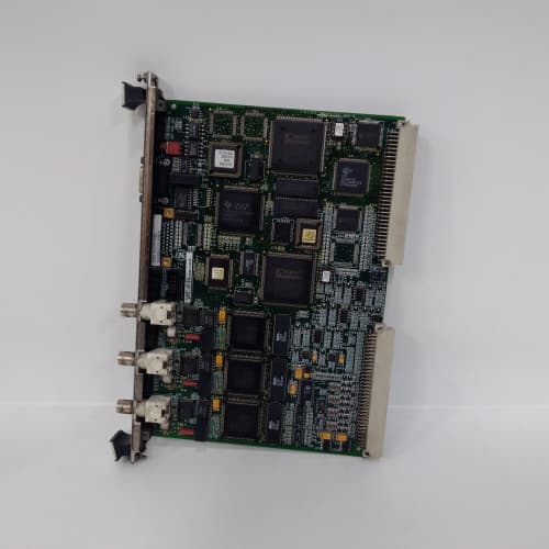
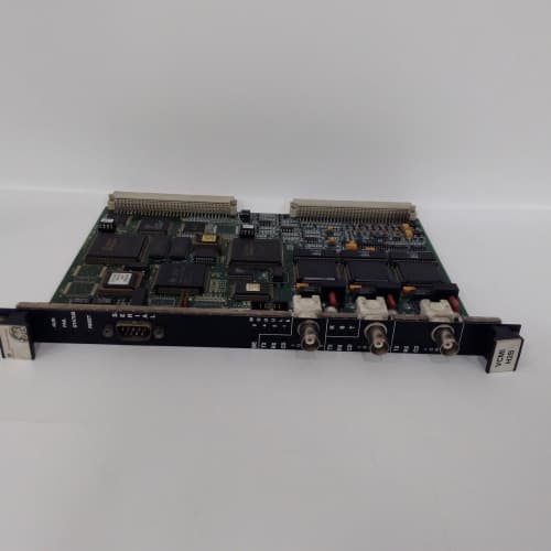
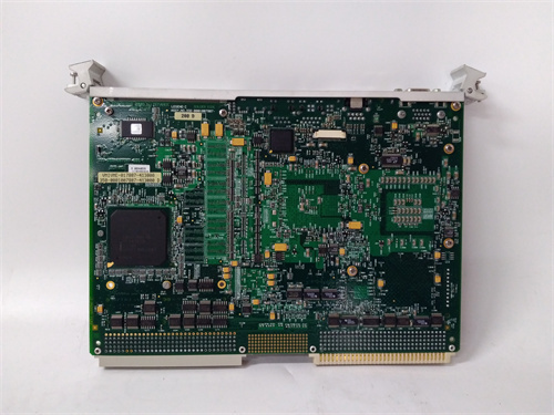
| Form Factor | 6U VME64x (160 × 233 mm), single-slot width |
| Indicators | LED for each channel (signal OK), channel status, overspeed trip status, module health |
| Operating Temp | 0 °C to +60 °C |
| Power Draw | 10 W typical (+5 V / +3.3 VDC) |
| Connectors | Front-panel 24-pin terminal block (screw-type) for sensor wiring |
| Diagnostic Memory | Non-volatile fault logging — stores last 500 events with timestamps |
Advantages & Distinctive Features
-
Redundant Speed Measurement: 3 independent channels enable 2-out-of-3 voting logic for overspeed protection—ensuring trip integrity while preventing false trips from single-channel failure.
-
Fast Response: <5 ms overspeed trip detection meets API 670 requirements for turbine overspeed protection.
-
Wide Sensor Compatibility: Accepts magnetic pickups, proximity probes, and tachometer signals—flexible for different turbine installations.
-
High Accuracy: ±0.01% reading ensures precise speed measurement for governor control and efficiency calculations.
-
Integrated Protection Logic: On-board overspeed, under-speed, and rate-of-change detection reduces processor board workload.
-
Programmable Scaling: User-configurable scaling (e.g., pulses per revolution) for different turbine configurations.
-
Built-in Self-Test: Continuous sensor health monitoring (signal presence, low amplitude detection) prevents false trips.
-
Hot-Swappable: Supports removal and replacement without powering down the rack.
-
Direct Retrofit: Replaces older VSPA series boards.
Application Fields
-
Gas Turbines: Overspeed protection, speed measurement for governor control, acceleration monitoring
-
Steam Turbines: Overspeed protection, speed measurement for synchronization, zero-speed detection for turning gear
-
Generators: Speed measurement for grid synchronization, overspeed protection
-
Compressors: Speed monitoring for variable-speed drives and surge protection
-
Diesel Engines: Speed measurement and overspeed protection for emergency generators
-
Pumps and Fans: Speed monitoring for performance optimization
Comparison with Competing Products
| Feature | GE IS200VSPAH1A | Competitor A (Bently Nevada 3500/50) | Competitor B (Rockwell XM-140) |
|---|---|---|---|
| Speed Channels | 3 (redundant) | 1 | 1 |
| Sensor Support | Magnetic/prox/tacho | Magnetic/prox | Magnetic/prox |
| Response Time | <5 ms | <10 ms | <15 ms |
| Voting Logic | 2-out-of-3 | 1-out-of-1 | 1-out-of-1 |
| Accuracy | ±0.01% | ±0.02% | ±0.05% |
| Fault Logging | 500 events | 100 events | No |
| Hot-Swappable | Yes | No | Yes |
The GE IS200VSPAH1A offers superior redundancy, faster response, and integrated voting logic—making it the ideal solution for critical overspeed protection in single VME slot.
Selection Guidelines
-
When to choose: Any Mark VIe application requiring reliable speed measurement and overspeed protection—gas turbines, steam turbines, generators, or compressors.
-
Sensor Selection: Verify field sensors are compatible (magnetic pickup requires 100 mV–100 V signal; proximity probe requires 5–24 VDC signal). Ensure sensor cable length meets specifications (<300 m for magnetic, <100 m for proximity).
-
Redundancy Configuration: Use all 3 channels with 2-out-of-3 voting logic for maximum protection integrity. At minimum, use 2 channels in 1-out-of-2 configuration.
-
Scaling Configuration: Enter correct pulses per revolution (gear teeth count) in Toolbox ST for accurate RPM measurement.
-
Trip Level Setting: Configure overspeed trip setpoint per turbine manufacturer specifications (typically 110–115% of rated speed).
-
Rate-of-Change Monitoring: Configure acceleration limit to detect runaway acceleration before overspeed trip activates.
-
Compatibility: Fits all Mark VIe VME64x racks. Requires processor board (VPRO series) with I/O Net connectivity and ControlST v6.0 or higher.
Operational Precautions
-
Wiring: Follow GE wiring diagrams (GEH-6810)—correct polarity and shield grounding essential. Use shielded twisted-pair cables for sensor wiring; ground the shield at the terminal board only.
-
Sensor Gap Setting: For proximity probes, verify the air gap is within specified range and bias voltage is correct.
-
Speed Calibration: Verify speed reading against a known reference (e.g., portable tachometer) during commissioning.
-
Overspeed Testing: Perform simulated overspeed tests (e.g., using a function generator) to verify trip logic and response time.
-
Voting Logic Verification: Test failure scenarios (simulate one channel failure) to verify 2-out-of-3 logic operates correctly.
-
LED Diagnostics: Green = signal OK, Amber = marginal signal, Red = channel fault or overspeed condition.
-
Fault Log: Access 500-event log via Toolbox ST for post-event analysis.
-
Hot-Swap Procedure: When replacing a GE IS200VSPAH1A under power, remove and insert slowly to avoid inrush spikes.
-
Spare Stock: Maintain at least one spare GE IS200VSPAH1A per 3–4 active racks—critical for turbine protection.
-
Annual Verification: Perform speed and overspeed tests during scheduled outages; document response times and compare with baseline.
-
Firmware Updates: Ensure the GE IS200VSPAH1A is in “standby” mode during updates.
-
ESD Handling: Handle by edges only using grounded wrist straps and ESD-safe workstations.
A-B 1746-NO4V
BOSCH CL200ZE200-DP (1070078883-109)
Reviews
There are no reviews yet.