
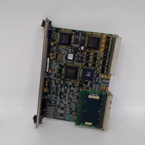
Description
Product Parameters
| Parameter | Specification |
|---|---|
| Brand / Series | GE Mark VIe Speedtronic |
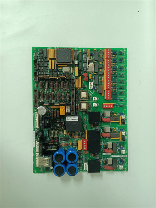
| Model | IS200TRLYH1C |
| Relay Outputs | 24 isolated channels (Form C, SPDT) — upgraded from 16 channels |
| Contact Rating | 8A @ 250 VAC / 30 VDC (resistive load) |
| Switching Voltage | 250 VAC / 30 VDC maximum |
| Switching Current | 8A maximum per channel |
| Inrush Capability | 15A for 50 ms (motor/inductive loads) |
| Coil Voltage | 24 VDC (internally supplied from Mark VIe rack) |
| Coil Current | 40 mA per relay (960 mA total maximum) |
| Response Time | < 8 ms (energize), < 4 ms (de-energize) |
| Electrical Life | 150,000 operations at rated load |
| Mechanical Life | 1,500,000 operations (no load) |
| Suppression | Built-in flyback diodes (DC loads), RC snubbers (AC loads), and MOV (transient suppression) |
| Isolation | 1500 VAC (channel-to-channel and field-to-system) |
| Diagnostics | Coil open-circuit detection, coil short-circuit detection, welded contact monitoring, contact wear monitoring |
| Status Indication | 24 green LEDs (output energized), 24 red LEDs (fault per channel), 2 red summary fault LEDs |
| Operating Temperature | –30°C to +65°C |
| Storage Temperature | –55°C to +85°C |
| Mounting | VME rack-mount terminal board with front-panel I/O connectors |
| Backplane Interface | VME64x (A24/A32, D16/D32/D64) |
| EMC Compliance | IEC 61000-4 Level 4 |
Advantages & Key Features
-
Maximum Channel Density: 24 isolated relay outputs in a single VME slot—the highest channel density in the Mark VIe relay output terminal family, providing 50% more channels than IS200TRLYH1B (16 channels). Ideal for large turbines with extensive actuator control requirements.
-
High Contact Rating: 8A per channel with 15A inrush capability enables direct control of large solenoids, contactors, and valve actuators.
-
Enhanced Suppression: Integrated flyback diodes, RC snubbers, and MOVs protect relay contacts and driver circuits.
-
Fast Response: < 8 ms energize and < 4 ms de-energize times ensure precise control.
-
Comprehensive Diagnostics: Coil open/short, welded contact, and contact wear monitoring per channel enable predictive maintenance.
-
High-Density Status Indication: 24 green/red LEDs enable rapid on-site troubleshooting.
-
ToolboxST Integration: Full configuration, monitoring, and diagnostics via GE ToolboxST.
-
Drop-In Replacement: Direct replacement for IS200TRLYH1B and earlier relay output terminal boards.
Application Fields
-
Gas & Steam Turbines (GE Frame 6B/7EA/9E/HA): Fuel gas shut-off valves, emergency stop solenoids, alarm annunciators, lube oil pump starters, generator breaker trip coils, cooling fan starters, auxiliary system actuators.
-
Combined Cycle Plants: Steam turbine extraction valves, bypass actuators, HRSG damper controls, condensate pump starters.
-
Compressor Stations: Anti-surge valve solenoids, discharge blow-down valves, station shutdown relays.
-
Aeroderivative Turbines: Fuel control solenoids, bleed valve actuators, oil temperature control.
Comparison with Competing Products
| Feature | GE IS200TRLYH1C | GE IS200TRLYH1B (16-ch) | GE IS200TRLYH1BGF (24-ch, 10A) | Competitor A (Relay Output) | Competitor B (Relay Module) |
|---|---|---|---|---|---|
| Relay Outputs | 24 isolated | 16 isolated | 24 isolated | 8 isolated | 8 isolated |
| Contact Rating | 8A (15A inrush) | 8A (15A inrush) | 10A (20A inrush) | 5A | 2A |
| Suppression | Flyback, RC, MOV | Flyback, RC, MOV | Flyback, RC, enhanced MOV, EMI filter | External required | External required |
| Diagnostics | Coil open/short, welded, wear | Coil open/short, welded, wear | Coil open/short, welded, wear, reference, EMI | Coil open only | None |
| Isolation | 1500 VAC | 1500 VAC | 2000 VAC | 1000 VAC | 500 VDC |
| Operating Temp | –30°C to +65°C | –30°C to +65°C | –40°C to +70°C | 0°C to 50°C | 0°C to 60°C |
Key Advantage: IS200TRLYH1C provides 24 isolated relay outputs—the highest channel density in the Mark VIe relay output terminal family—with 8A contact rating, 15A inrush capability, built-in suppression, and comprehensive diagnostics including contact wear monitoring, making it ideal for large turbine systems requiring extensive high-current actuator control.
Selection Guidelines & Recommendations
-
Channel Count: 24 relay outputs per board—ideal for large turbine systems.
-
Contact Rating: Confirm load requirements do not exceed 8A @ 250 VAC or 8A @ 30 VDC. For inductive loads, de-rate to 5A.
-
Inrush Capability: 15A for 50 ms—verify load inrush does not exceed this.
-
Load Protection: For highly inductive DC loads, add external varistors.
-
Diagnostic Configuration: Enable welded contact and wear monitoring for critical safety circuits.
-
Controller Firmware: Requires Mark VIe processor firmware v8.0 or later.
-
Spare Strategy: Keep one spare per turbine; lead times 6–10 weeks.
-
Retrofit: Direct replacement—regenerate configuration in GE ToolboxST for 24-channel mapping.
Important Cautions
-
No Hot-Swap: De-energize rack before insertion/removal.
-
Wiring Polarity: For DC loads, observe correct polarity—reverse polarity shorts through the flyback diode.
-
Contact Protection: For loads exceeding 8A, use external contactors.
-
Grounding: Connect chassis ground at single star point.
-
Shield Termination: Ground output cable shields only at cabinet end.
-
ESD Handling: Use grounded wrist straps; field repair not possible.
-
Temperature Rating: Verify cabinet ambient does not exceed +65°C or fall below –30°C.
-
Welded Contact Detection: Refer to GE wiring diagram IS200TRLYH1C-DWG.
-
Wear Monitoring: Set operational thresholds in GE ToolboxST for maintenance alerts.
-
Power Supply: Ensure adequate current for all active outputs (40 mA × 24 = 960 mA max).
-
Channel Mapping: With 24 channels, verify field wiring maps to correct ToolboxST channel numbers.
TRICONEX 3008 汾
A-B 1606-XL240E
A-B 1203-FM1
HONEYWELL CC-TAIN01


Reviews
There are no reviews yet.