
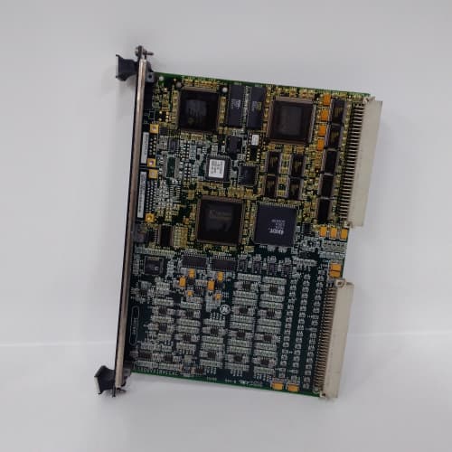
Description
Product Parameters
| Parameter | Specification |
|---|---|
| Brand / Series | GE Mark VIe Speedtronic |
| Model | IS200SRLYH2AAA |
| Output Channels | 16 isolated Form C relays (SPDT, normally open/normally closed) |
| Contact Rating | 8A @ 250 VAC / 8A @ 30 VDC (resistive load) — upgraded from 5A on IS200SRLYH2A |
| Switching Voltage | 250 VAC / 30 VDC maximum |
| Switching Current | 8A maximum per channel |
| Inrush Current Capability | 15A for 50 ms (motor/inductive loads) |
| Coil Voltage | 24 VDC (internally supplied from Mark VIe rack) |
| Coil Current | 40 mA per relay (640 mA total maximum) |
| Response Time | < 8 ms (energize), < 4 ms (de-energize) |
| Electrical Life | 150,000 operations at rated load (improved from 100,000) |
| Mechanical Life | 1,500,000 operations (no load) |
| Suppression | Built-in flyback diodes (DC loads), RC snubbers (AC loads), and MOV (transient voltage suppression) |
| Diagnostics | Coil open-circuit detection, coil short-circuit detection, welded contact detection, contact wear monitoring |
| Redundant Coil Drivers | Dual drivers per channel for fail-safe operation |
| Status Indication | 16 green LEDs (energized), 16 red LEDs (fault per channel), 1 yellow LED (summary fault) |
| Isolation | 2000 VAC (channel-to-channel and coil-to-contacts) — upgraded from 1500 VAC |
| Operating Temperature | –30°C to +65°C |
| Storage Temperature | –55°C to +85°C |
| Mounting | VME 6U rack-mount with front-panel terminal connectors |
| Backplane Interface | VME64x (A24/A32, D16/D32/D64) |
| Alarm Outputs | 2 dedicated fault summary relays (Form C) — upgraded from 1 on IS200SRLYH2A |
| EMC Compliance | Enhanced EMI filtering per IEC 61000-4-2, -4, -5 (Level 4) |
Advantages & Key Features
-
Higher Contact Rating: IS200SRLYH2AAA provides 8A per channel (upgraded from 5A on IS200SRLYH2A), enabling direct control of larger solenoids, contactors, and valve actuators without external intermediate relays. The 15A inrush capability handles motor and inductive startup currents reliably.
-
Enhanced Diagnostics & Monitoring: Each relay channel includes coil open/short detection, welded contact detection, and contact wear monitoring (tracking cumulative operations). All diagnostic data is reported via VME backplane to GE ToolboxST for predictive maintenance. This advanced diagnostic suite is unique to IS200SRLYH2AAA within the Mark VIe relay family.
-
Redundant Coil Drivers: Dual independent coil drivers per channel provide fail-safe operation. If one driver fails, the second continues to operate the relay, ensuring critical turbine functions remain available—a key advantage over single-driver designs.
-
Enhanced Load Suppression: Integrated flyback diodes for DC loads, RC snubbers for AC loads, and metal-oxide varistors (MOV) for transient voltage suppression protect both the relay contacts and the board’s driver circuits from voltage spikes and arcing, extending electrical life and reducing field maintenance.
-
Fast Response Times: < 8 ms energize and < 4 ms de-energize times ensure precise control of high-speed turbine actuators and trip solenoids, meeting the demanding response requirements of overspeed and emergency shutdown systems.
-
Dual Fault Summary Relays: Two dedicated Form C relays provide redundant hardware-based alarm outputs that can trigger external annunciators or emergency shutdown logic, independent of the main processor—essential for safety-certified installations and TMR applications.
-
Enhanced Isolation: 2000 VAC isolation (upgraded from 1500 VAC) provides superior protection for the Mark VIe backplane and processor from field wiring faults and surges.
-
Visual Status Indication: Each channel has dual LED indicators—green when energized, red when a fault is detected. A yellow summary fault LED provides quick visual indication of any channel fault, enabling rapid on-site troubleshooting.
-
ToolboxST Integration: Full configuration and diagnostics via GE ToolboxST software, enabling online relay testing, contact wear monitoring, and predictive maintenance alerts.
-
Drop-In Replacement: Direct replacement for earlier GE relay boards such as IS200SRLYH1A, IS200SRLYH1, and IS200SRLYH2A, with identical mounting holes, connectors, and backplane addressing, but with enhanced capabilities.
Application Fields
-
Gas & Steam Turbines (GE Frame 6B/7EA/9E/HA): Controls fuel gas shut-off valves, emergency stop solenoids, alarm annunciators, lube oil pump starters, generator breaker trip coils, and cooling fan starters.
-
Combined Cycle Plants: Manages steam turbine extraction valves, bypass actuators, HRSG damper controls, and condensate pump starters.
-
Compressor Stations: Controls anti-surge valve solenoids, discharge blow-down valves, station shutdown relays, and cooling system actuators.
-
Oil & Gas Pipelines: Used for valve positioning, pump motor starters, emergency shutdown (ESD) systems, and fire protection actuators.
-
Hydropower Plants: Controls wicket gate actuators, brake solenoids, alarm indicators, and emergency gate release mechanisms.
-
Nuclear Power Plants: Used in auxiliary turbine systems where redundant coil drivers and enhanced diagnostics are mandated by regulatory requirements.
Comparison with Competing Products
| Feature | GE IS200SRLYH2AAA | GE IS200SRLYH2A (Previous Gen) | Competitor A (Emerson Relay Module) | Competitor B (Siemens Relay Output) |
|---|---|---|---|---|
| Output Channels | 16 isolated Form C | 16 Form C | 8 Form C | 8 Form A |
| Contact Rating | 8A @ 250 VAC / 30 VDC | 5A @ 250 VAC / 30 VDC | 2A @ 250 VAC / 24 VDC | 5A @ 250 VAC / 24 VDC |
| Inrush Capability | 15A (50 ms) | 8A (50 ms) | 4A (50 ms) | 8A (50 ms) |
| Diagnostics | Coil open/short, welded contact, wear monitoring | Coil open/short, welded contact | Coil open only | None |
| Redundant Coil Drivers | Yes (dual per channel) | No | No | No |
| Response Time | < 8 ms / < 4 ms | < 10 ms / < 5 ms | < 15 ms / < 10 ms | < 20 ms / < 10 ms |
| Suppression | Flyback, RC snubber, MOV | Flyback, RC snubber | External required | External required |
| Fault Summary Relays | 2 (redundant) | 1 | No | No |
| Isolation | 2000 VAC | 1500 VAC | 1000 VAC | 500 VDC |
| EMC Filtering | IEC Level 4 | Level 2 | Level 2 | Level 1 |
| Operating Temp | –30°C to +65°C | –30°C to +65°C | 0°C to 50°C | 0°C to 60°C |
Key Advantage: IS200SRLYH2AAA delivers the highest contact rating (8A), inrush capability (15A), and diagnostic sophistication in the Mark VIe relay family. Its redundant coil drivers, dual fault summary relays, enhanced isolation, and comprehensive diagnostics (including contact wear monitoring) make it the most reliable and maintainable relay output solution for critical turbine applications. These features are unmatched by competitor products, which typically offer lower channel density, inferior diagnostics, and no redundancy or wear tracking.
Selection Guidelines & Recommendations
-
Contact Rating Verification: Confirm that the current and voltage requirements of your field devices do not exceed 8A @ 250 VAC or 8A @ 30 VDC per channel. For inductive loads (solenoids, motors), the 15A inrush capability handles startup surges—but for continuous loads exceeding 8A, use external contactors to protect IS200SRLYH2AAA.
-
Load Type Consideration: The enhanced suppression (flyback + RC + MOV) covers most DC and AC loads. For highly inductive DC loads with long cable runs (e.g., large solenoids > 50 meters), consider adding external varistors at the load side to further reduce voltage spikes.
-
Diagnostic Configuration: Enable welded contact detection and contact wear monitoring via GE ToolboxST for all critical safety circuits (fuel shut-off, overspeed trip, ESD). This feature uses a readback circuit; refer to GE wiring diagram IS200SRLYH2AAA-DWG for correct implementation.
-
Redundancy Planning: For TMR systems, deploy three IS200SRLYH2AAA boards per critical output function, with outputs wired in 2-out-of-3 voting configurations. The redundant coil drivers on each board add an extra layer of fault tolerance within the TMR architecture.
-
Controller Firmware: Ensure your Mark VIe main processor (e.g., IS420UCSBH1A, IS420UCSCH1A, IS200SPROH2ADD) is running firmware v9.0 or later for full diagnostic support, including contact wear monitoring and redundant driver status readback on IS200SRLYH2AAA.
-
ToolboxST Configuration: In GE ToolboxST, assign each output channel to the appropriate control logic. Configure fail-safe behavior—define whether relays de-energize on processor loss of communication (normally preferred for safety circuits). Set wear monitoring thresholds to receive maintenance alerts when contacts approach end-of-life.
-
Wiring Guidelines: Use shielded twisted-pair cables for output wiring, especially if extending beyond 10 meters. For inductive loads, route power and signal cables separately to minimize EMI. Terminate shields only at the Mark VIe cabinet ground.
-
Spare Strategy: For critical plants with TMR configurations, maintain at least two spare IS200SRLYH2AAA units per turbine system. Lead times typically 8–12 weeks due to specialized components and extensive factory testing.
-
Retrofit: Direct replacement for IS200SRLYH1A, IS200SRLYH1, and IS200SRLYH2A—no chassis or cable changes required. However, configuration files must be updated in GE ToolboxST to access the enhanced diagnostics (wear monitoring, redundant driver status, dual fault relays). The new configuration enables predictive maintenance capabilities not available on earlier models.
Important Cautions
-
No Hot-Swap: IS200SRLYH2AAA is not hot-swappable. Always de-energize the Mark VIe rack before insertion/removal to prevent backplane damage and protect the sensitive diagnostic circuits.
-
Load Protection: Although built-in suppression is provided, external loads exceeding 8A or highly inductive loads can weld relay contacts. Use external contactors for continuous loads > 8A to protect IS200SRLYH2AAA.
-
Wiring Polarity: For DC loads, observe correct polarity—the flyback diode is polarity-sensitive. Reverse polarity will short the supply through the diode and damage the relay coil driver or the dual driver redundancy logic.
-
Contact Life Management: Electrical life at rated load is 150,000 operations. For frequent cycling applications (e.g., modulating valves > 10 cycles per minute), consider using solid-state output modules instead to avoid premature contact wear. Use the wear monitoring feature in GE ToolboxST to track cumulative operations and plan preventive maintenance.
-
Welded Contact Detection Wiring: To enable this diagnostic feature, the load circuit must include a voltage detection resistor and an analog input to the Mark VIe system. Refer to GE wiring diagram IS200SRLYH2AAA-DWG for correct implementation. Improper wiring will generate false faults.
-
Redundant Driver Testing: The dual coil drivers are factory-tested and matched. Do not attempt to test or activate individual drivers manually via GE ToolboxST—the board automatically switches to the redundant driver upon fault detection. Manual intervention can cause driver mismatch and false diagnostics.
-
Grounding: Connect the Mark VIe cabinet ground at a single star point to avoid ground loops that can induce false coil fault readings or interfere with welded contact detection.
-
ESD Handling: Use grounded wrist straps during handling; the advanced driver circuits and diagnostic logic are ESD-sensitive. Field repair is not possible due to conformal coating.
-
EMI Environment: Although IS200SRLYH2AAA provides enhanced EMI filtering (IEC Level 4), avoid routing output cables parallel to high-voltage AC lines (e.g., 480 VAC motor feeds) over long distances. If unavoidable, maintain separation of at least 300 mm or use metal conduit for the output cables.
-
Firmware Lock: The board’s diagnostic features and suppression characteristics are factory-calibrated. Do not attempt firmware updates via USB or ToolboxST independently—IS200SRLYH2AAA is factory-locked. Unauthorized modifications will require return to a GE service center.
A-B 1756-DNB
MR-J2M-20DU
A-B 1761-NET-ENI
MR-J2M-20DU

Reviews
There are no reviews yet.