
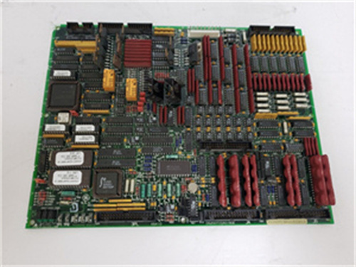
.jpg "IS200WETBH1ABA(3)")
Description
Technical Specifications
| Parameter | Specification |
|---|---|
| Manufacturer | General Electric |
| Model | IS200EPDMG1AAA |
| Communication Interfaces | 2× configurable ports (RS-485 / fieldbus) |
| Supported Protocols | Modbus RTU, DNP3, GE proprietary protocols |
| Power Distribution Functions | Breaker monitoring, power quality, switchgear coordination |
| Motor Control Functions | Start/stop, status monitoring, protection coordination |
| Supported Equipment | Motor control centers, switchgear, breakers, power meters |
| Power | +5V DC / 2.0A, ±15V DC / 0.4A |
| Temp Range | -30°C to +65°C |
| MTBF | > 110,000 hours |
| Suffix Meaning | “AAA” = specific power distribution/motor configuration |
Advantages and Key Features
Combined Power Distribution and Motor Gateway: The IS200EPDMG1AAA integrates both power distribution monitoring and motor control functions in a single board, reducing system complexity.
Breaker and Switchgear Interface: Provides direct communication with breakers, switchgear, and power monitoring devices.
Motor Control Integration: The IS200EPDMG1AAA enables start/stop and status monitoring of auxiliary motors.
Multi-Protocol Support: Supports Modbus RTU and DNP3 for plant-wide integration.
Pre-Configured Firmware: “AAA” firmware reduces commissioning time.
Application Fields and Case Studies
Used in combined-cycle plants for auxiliary power distribution monitoring, motor control center integration, and breaker/switchgear coordination. In a 500 MW plant, the IS200EPDMG1AAA monitored feeder breakers and controlled auxiliary motors from a single interface, simplifying system architecture.
Comparison with Competing Products
| Dimension | IS200EPDMG1AAA | IS200EPCTG1AAA | IS200EMCSG1AAB |
|---|---|---|---|
| Primary Function | Power distribution + motor | Transformer/converter | Motor gateway |
| Breaker/Switchgear | Yes | No | No |
| Motor Control | Yes | No | Yes |
| VME Integration | Direct | Direct | Direct |
Selection Recommendations
Choose IS200EPDMG1AAA when your installation requires both power distribution monitoring and motor control integration. Select over dedicated boards when system consolidation is desired. Verify “AAA” firmware matches your equipment. Deploy redundant boards for critical power paths.
Precautions and Important Notes
Use ESD-safe handling. Verify communication wiring and settings. Confirm “AAA” firmware supports your switchgear and motor control equipment. Never interrupt firmware updates. Board draws 2.0A – verify rack power capacity. Document all configurations. Store spares in anti-static packaging. Do not mix variants in redundant pairs. Allow 30 seconds boot time. Test both power monitoring and motor control functions during commissioning.
.jpg)
.jpg)
SCHNEIDER 140ARI03010
GE IC697MDL940F
GE IC670GBI002H



Reviews
There are no reviews yet.