
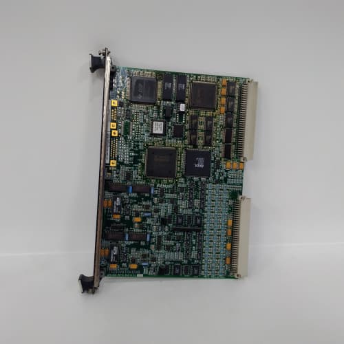
Description
Product Parameters
| Parameter | Specification |
|---|---|
| Brand / Series | GE Mark VIe Speedtronic |
| Model | IS200TCATH1A |
| Total Channels | 32 mixed inputs (configurable) |
| Thermocouple Inputs | Up to 16 channels (J, K, T, E, R, S, B) |
| Analog Inputs | Up to 16 channels (4–20 mA, 0–10 V, ±10 V selectable) |
| Thermocouple Range | ±100 mV |
| Analog Range | 0–20 mA, 4–20 mA, 0–5 V, 0–10 V, ±10 V |
| Cold-Junction Compensation | Built-in CJC sensor (accuracy ±0.5°C) |
| ADC Resolution | 24-bit delta-sigma (thermocouple), 16-bit SAR (analog) |
| Sampling Rate | 4–200 SPS (thermocouple), 10–500 SPS (analog) |
| Accuracy | TC: ±0.1% + ±1°C; Analog: ±0.1% FS |
| Loop Power | 24 VDC (externally supplied only) |
| Isolation | 1500 VAC (field-to-system) |
| CMRR | >100 dB @ 50/60 Hz |
| Diagnostics | Open-circuit, short-circuit, over/under-range, CJC fault, loop power fault |
| Status Indication | 32 green LEDs (channel active), 2 red LEDs (diagnostic fault summary) |
| Operating Temperature | –30°C to +65°C |
| Storage Temperature | –55°C to +85°C |
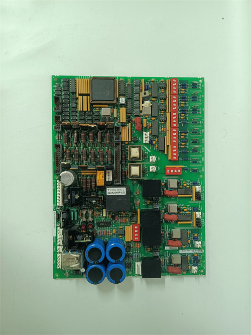
| Mounting | VME rack-mount terminal board with front-panel I/O connectors |
| Backplane Interface | VME64x (A24/A32, D16/D32/D64) |
| EMC Compliance | IEC 61000-4 Level 4 |
Advantages & Key Features
-
Mixed Input Flexibility: IS200TCATH1A combines thermocouple and analog inputs on a single board, eliminating the need for separate terminal boards for temperature and process variable monitoring. This simplifies system design and reduces rack space.
-
Configurable Channel Allocation: The channel configuration (thermocouple vs. analog) is software-configurable via GE ToolboxST, allowing up to 16 thermocouple and 16 analog inputs, or any mix in between, to match specific application requirements.
-
High Channel Density: 32 total inputs in a single VME slot—four times the density of competing 8-channel modules for both thermocouple and analog signals.
-
High-Precision CJC: Built-in CJC sensor with automatic compensation ensures thermocouple measurement accuracy.
-
24-Bit Thermocouple Conversion: High-resolution ADC delivers stable, noise-free temperature readings.
-
Programmable Analog Inputs: Each analog channel supports 4–20 mA, 0–10 V, or ±10 V inputs.
-
Comprehensive Diagnostics: Real-time open-circuit, short-circuit, over/under-range, CJC fault, and loop power fault detection per channel.
-
ToolboxST Integration: Full configuration, calibration, and diagnostics via GE ToolboxST.
-
Drop-In Replacement: Direct replacement for earlier GE mixed input terminal boards.
Application Fields
-
Gas & Steam Turbines (GE Frame 6B/7EA/9E/HA): Exhaust gas temperature (thermocouple) combined with fuel gas pressure (4–20 mA), steam pressure (4–20 mA), valve position feedback (0–10 V), and bearing temperature (thermocouple).
-
Combined Cycle Plants: HRSG superheater temperature (thermocouple) plus feedwater flow (4–20 mA), steam drum pressure (4–20 mA), and condensate temperature (thermocouple).
-
Compressor Stations: Discharge temperature (thermocouple) combined with suction pressure (4–20 mA) and vibration monitoring.
-
Aeroderivative Turbines: Exhaust temperature (thermocouple) plus fuel flow (4–20 mA), oil pressure (4–20 mA), and guide vane position (0–10 V).
Comparison with Competing Products
| Feature | GE IS200TCATH1A | Competitor A (Mixed I/O) | Competitor B (Separate TC + Analog) |
|---|---|---|---|
| Total Inputs | 32 mixed | 8 mixed | 16 (8 TC + 8 analog) |
| Thermocouple Types | J, K, T, E, R, S, B | J, K, T | J, K, T, E, R, S, B |
| Analog Input Types | 4–20 mA, 0–10 V, ±10 V | 4–20 mA only | 4–20 mA, 0–10 V |
| CJC Accuracy | ±0.5°C | ±1.2°C | ±0.5°C |
| Isolation | 1500 VAC | 1000 VAC | 1500 VAC |
| Operating Temp | –30°C to +65°C | 0°C to 50°C | –30°C to +65°C |
Key Advantage: IS200TCATH1A provides 32 mixed thermocouple and analog inputs—four times the density of competing modules—with flexible channel allocation, high-precision CJC, and comprehensive diagnostics, making it ideal for turbine applications requiring both temperature and process variable monitoring in a single board.
Selection Guidelines & Recommendations
-
Channel Configuration: Determine the required mix of thermocouple and analog inputs for your application. Configure the channel allocation in GE ToolboxST before commissioning.
-
Thermocouple Type: Verify your thermocouple types. IS200TCATH1A supports J, K, T, E, R, S, and B—configure per channel.
-
Analog Input Type: Configure 4–20 mA, 0–10 V, or ±10 V per analog channel in GE ToolboxST.
-
Loop Power: External 24 VDC supplies required for 2-wire transmitters—plan cabinet power distribution accordingly.
-
CJC Sensor Placement: The CJC sensor is located on the terminal block—maintain adequate airflow around it.
-
Controller Firmware: Requires Mark VIe processor firmware v7.5 or later.
-
Spare Strategy: Keep one spare per turbine; lead times 6–10 weeks.
-
Retrofit: Direct replacement—regenerate configuration in GE ToolboxST.
Important Cautions
-
No Hot-Swap: De-energize rack before insertion/removal.
-
Thermocouple Polarity: Reverse connection produces negative readings—verify polarity against terminal labeling.
-
Analog Polarity: Observe correct polarity for 4–20 mA loops and voltage inputs.
-
CJC Protection: Do not apply conformal coating or tape over the terminal block area—this insulates the CJC sensor.
-
Loop Power: External 24 VDC required—ensure supplies are connected.
-
Grounding: Connect AGND to Mark VIe system ground at single star point.
-
Shield Termination: Ground shields only at cabinet end.
-
ESD Handling: Use grounded wrist straps; field repair not possible.
-
Channel Mapping: With 32 mixed channels, verify field wiring maps to correct ToolboxST channel assignments.
-
Input Overload: Sustained analog input >30 V or >50 mA may damage input circuitry.
A-B 1756-IF8
SCHNEIDER 140CRA93200
BENTLY 330180-51-00


Reviews
There are no reviews yet.