
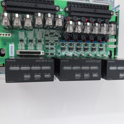
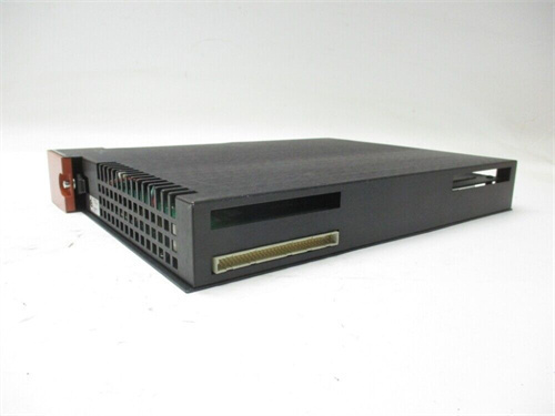
Description
Key Specifications
| Parameter | Specification |
|---|---|
| Output Channels | 4 isolated servo valve output channels |
| Output Types | 4–20 mA, 0–20 mA, ±20 mA, 0–10 V, ±10 V (software-selectable per channel) |
| Output Resolution | 16-bit DAC |
| Output Accuracy | ±0.05% of full scale |
| Output Drive Capacity | 20 mA @ 24 VDC (current mode); ±10 mA (voltage mode) |
| Output Load | 0–750 Ω (current mode); ≥2 kΩ (voltage mode) |
| Output Protection | Short-circuit protection, overcurrent limiting, output rate-of-change limiting (ramp control), feedback loss detection |
| Feedback Inputs | 4 differential analog feedback inputs (LVDT/RVDT/potentiometer) for position verification |
| Feedback Input Range | ±10 VDC, 0–10 VDC (software-selectable) |
| Feedback Resolution | 16-bit ADC |
| Isolation | 1500 VDC (output-to-backplane) |
| Diagnostics | 500-event fault log with timestamps and output snapshots |
| Communication | I/O Net (dual Ethernet ports for redundancy) |
| Form Factor | 6U VME64x (160 × 233 mm), single-slot width |
| Indicators | LED per output channel (command signal OK, fault), per feedback channel (signal OK), module health |
| Operating Temp | 0 °C to +60 °C |
| Power Draw | 15 W (+5 V / +3.3 VDC) |
| Connectors | Front-panel 32-pin terminal block with gold-plated contacts and captive washer screws |
Advantages & Distinctive Features
-
4 Independent Servo Valve Channels: Controls up to 4 servo/proportional valves per module—reduces rack space.
-
Flexible Output Configuration: Each channel individually configurable as 4–20 mA, 0–20 mA, ±20 mA, 0–10 V, or ±10 V—accommodates diverse valve types.
-
Integrated Feedback Inputs: 4 feedback inputs (LVDT/RVDT/potentiometer) for closed-loop position verification.
-
Output Rate-of-Change Limiting: Programmable ramping prevents sudden valve movements—reduces mechanical stress and process disturbances.
-
Output Short-Circuit Protection: Protects the module and valve driver circuitry.
-
Feedback Loss Detection: Automatic channel shutdown if feedback signal is lost—prevents runaway conditions.
-
16-Bit Resolution: High precision for fine fuel/steam flow control.
-
Gold-Plated Captive Washer Terminals: Corrosion-resistant and vibration-proof connections.
-
Hot-Swappable: No rack power-down for replacement.
-
Direct Retrofit: Replaces older SVCXH series boards.
Application Fields
-
Gas Turbines: Fuel control valves (gas and liquid), inlet guide vane (IGV) actuators
-
Steam Turbines: Steam admission valves, control valves, extraction valves, bypass valves
-
Compressors: Anti-surge control valves, inlet guide vanes
-
Combined Cycle: HRSG bypass valves, attemperator spray valves
-
Marine Applications: Propeller pitch control, fuel control valves
Comparison with Competitors
| Feature | GE IS205SVCXHG1A | Competitor A (Woodward SPM-D2) | Competitor B (Siemens 6ES7-332) |
|---|---|---|---|
| Output Channels | 4 | 2 | 2 |
| Output Configurability | Current/Voltage (±20 mA, ±10 V) | Current only | Current only |
| Feedback Inputs | 4 | 2 | None |
| Output Resolution | 16-bit | 14-bit | 14-bit |
| Output Accuracy | ±0.05% | ±0.1% | ±0.2% |
| Ramp/Rate Limiting | Yes (programmable) | Yes | No |
| Feedback Loss Detection | Yes | No | No |
| Hot-Swappable | Yes | No | No |
The GE IS205SVCXHG1A offers superior channel density, flexibility, integrated feedback, and precision—making it the ideal solution for servo valve control in critical turbine applications.
Selection Guidelines
-
When to choose: Any Mark VIe application requiring precise servo/proportional valve control with position feedback—gas turbines, steam turbines, compressors.
-
Output Configuration: Select 4–20 mA for most servo valves; ±20 mA for high-noise environments; ±10 V for valves with local amplifiers.
-
Feedback Sensor Selection: Verify LVDT/RVDT/potentiometer output range matches input range (±10 V recommended).
-
Ramp Rate Setting: Set ramp rate per valve manufacturer specification to avoid mechanical shock.
-
Compatibility: Fits all Mark VIe VME64x racks. Requires ControlST v6.0 or higher.
Operational Precautions
-
Wiring: Follow GE wiring diagrams—correct polarity and shield grounding essential. Use shielded twisted-pair cables; ground shield at terminal board only.
-
Feedback Polarity: Verify feedback sensor polarity in Toolbox ST—incorrect polarity results in reverse-acting control.
-
Calibration: Factory calibrated—verify output current/voltage against a known reference during commissioning.
-
Ramp Test: Verify ramp rates by commanding step changes and observing valve response.
-
Feedback Loss Test: Simulate feedback loss (open circuit) to verify channel shutdown and alarm logic.
-
LED Diagnostics: Green = normal; Amber = marginal/feedback loss; Red = output fault/overcurrent.
-
Fault Log: Access 500-event log via Toolbox ST for post-event analysis.
-
Hot-Swap: Remove/insert slowly under power—processor auto-recognizes new module.
-
Spare Stock: Maintain 1 spare per 3–4 racks.
-
Annual Verification: Verify output accuracy against known reference during outages; document drift trends.
-
Firmware Updates: Ensure the GE IS205SVCXHG1A is in “standby” mode during updates.
-
ESD: Handle by edges only with grounded wrist strap.
A-B 1746-P4
Bachmann FM212
WESTINGHOUSE 1C31227G01
B&R ECPNC3-0




Reviews
There are no reviews yet.