
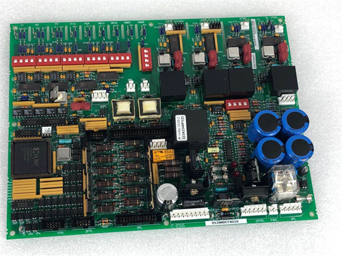
.jpg "IS200WETBH1ABA(5)")
Description
Key Specifications
| Parameter | Specification |
|---|---|
| Output Channels | 16 discrete outputs (high-side or low-side configurable) |
| Output Type | Solid-state (MOSFET) outputs |
| Output Voltage Rating | 24 VDC nominal (18–32 VDC) |
| Output Current Capacity | 2 A per channel (continuous), 5 A per channel (inrush for 100 ms) |
| Total Output Current | 16 A maximum (module total) |
| Output Protection | Short-circuit protection, overcurrent limiting, over-temperature protection, inductive load clamp (flyback diode) |
| Diagnostic Feedback | Load current monitoring per channel (open/short detection), output state feedback |
| Isolation | 1500 VDC (output-to-backplane) |
| Communication | I/O Net (dual Ethernet ports for redundancy) |
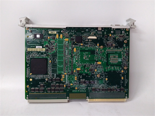
| Form Factor | 6U VME64x (160 × 233 mm), single-slot width |
| Indicators | LED per channel (output state), module health, communication status |
| Operating Temp | 0 °C to +60 °C |
| Power Draw | 10 W typical (+5 V / +3.3 VDC) + external 24 VDC field power (supplied separately) |
| Connectors | Front-panel 32-pin terminal block (screw-type) for field wiring |
| Diagnostic Memory | Non-volatile fault logging — stores last 500 events with timestamps |
Advantages & Distinctive Features
-
16 High-Capacity Outputs: Controls up to 16 solenoids/actuators per module—reduces rack space and cost.
-
High Inrush Capability: 5 A per channel for 100 ms handles solenoid inrush currents without nuisance trips.
-
Integrated Diagnostics: Per-channel load current monitoring detects open/short circuits and identifies degraded solenoids (increased current draw).
-
Output State Feedback: Provides actual output state (on/off) to the processor for confirmation and sequence verification.
-
Inductive Load Clamping: Built-in flyback diodes protect outputs from voltage spikes when de-energizing solenoids.
-
Short-Circuit Protection: Auto-shutdown prevents module damage from wiring faults; auto-retry after fault clears.
-
Hot-Swappable: Supports removal and replacement without powering down the rack.
-
Direct Retrofit: Replaces older VSVO series boards.
Application Fields
-
Gas Turbines: Trip solenoids, fuel shut-off valves, purge/drain valves, start-up bleed valves
-
Steam Turbines: Emergency stop valves (ESV), control valve trip solenoids, extraction valves
-
Compressors: Anti-surge blow-off valves, suction/discharge isolation valves
-
Generators: H2 supply shut-off valves, seal oil system valves
-
Combined Cycle: HRSG drain valves, feedwater isolation valves
-
Marine: Fuel isolation valves, ballast valve controls
Comparison with Competing Products
| Feature | GE IS200VSVOH1A | Competitor A (Siemens 6ES7-322) | Competitor B (Rockwell 1794-OB16) |
|---|---|---|---|
| Output Channels | 16 | 16 | 16 |
| Current/Channel | 2 A (continuous), 5 A (inrush) | 0.5 A | 2 A |
| Inrush Support | Yes (100 ms) | No | No |
| Load Monitoring | Per-channel current sensing | No | No |
| Inductive Clamp | Built-in | External required | Built-in |
| Short-Circuit Protection | Yes (auto-retry) | Yes (manual reset) | Yes (manual reset) |
| Isolation | 1500 VDC | 1500 VDC | 1500 VDC |
| Hot-Swappable | Yes | No | Yes |
The GE IS200VSVOH1A offers superior inrush current capability and per-channel diagnostics—making it ideal for solenoid valve control applications requiring reliability and maintainability.
Selection Guidelines
-
When to choose: Any Mark VIe application requiring on/off solenoid valve or actuator control—gas turbines, steam turbines, compressors, generators.
-
Load Verification: Verify solenoid/actuator inrush and holding currents do not exceed 5 A inrush or 2 A continuous per channel.
-
Field Power Supply: Provide a dedicated 24 VDC field power supply (external to the module) with sufficient capacity for all solenoids simultaneously.
-
Wiring Considerations: Use appropriate wire gauge (minimum 18 AWG) for 2 A continuous load; oversize for long cable runs.
-
Diode Installation: For solenoids without internal flyback diodes, the module’s built-in clamp provides protection—no external diodes required.
-
Compatibility: Fits all Mark VIe VME64x racks. Requires processor board (VPRO series) with I/O Net connectivity and ControlST v6.0 or higher.
Operational Precautions
-
Wiring: Follow GE wiring diagrams (GEH-6816)—correct polarity essential for external field power connection. Use shielded cables for long runs.
-
Field Power: Ensure external 24 VDC power supply is properly sized and fused (recommend 20 A fuse per rack). Do not power solenoids from the module backplane.
-
Load Current Monitoring: Use Toolbox ST to view per-channel current readings—trend increasing current over time indicates solenoid wear or impending failure.
-
Short-Circuit Testing: Simulate a short circuit to verify auto-shutdown and auto-retry functionality during commissioning.
-
LED Diagnostics: Green = output on, Amber = output off with fault (short/open), Red = module fault. Check fault log for details.
-
Fault Log: Access 500-event log via Toolbox ST for post-event analysis.
-
Hot-Swap Procedure: When replacing a GE IS200VSVOH1A under power, remove and insert slowly to avoid inrush spikes.
-
Spare Stock: Maintain at least one spare GE IS200VSVOH1A per 3–4 active racks—critical for shutdown and isolation valve availability.
-
Annual Verification: Test each output by cycling solenoids during outages; monitor current draw and switching response times.
-
Firmware Updates: Ensure the GE IS200VSVOH1A is in “standby” mode during updates.
-
ESD Handling: Handle by edges only using grounded wrist straps and ESD-safe workstations.
-
Environmental: Ensure ambient temperature does not exceed 60 °C—derate current capacity above 50 °C (reduce total output current to 12 A max).
.jpg)
.jpg)
A-B 1746-HSRV
A-B 1747-L542
GE IC693ALG223
A-B 1756-OF8


Reviews
There are no reviews yet.