
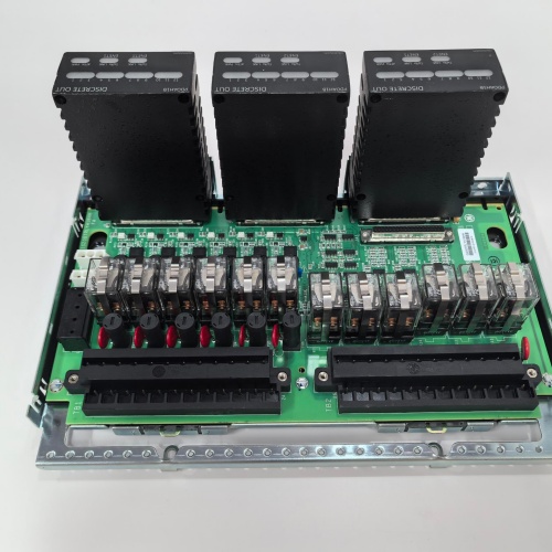
Description
Product Parameters
| Parameter | Specification |
|---|---|
| Brand / Series | GE Mark VIe Speedtronic |
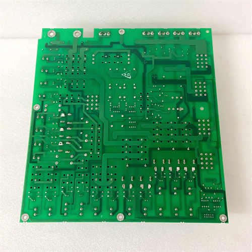
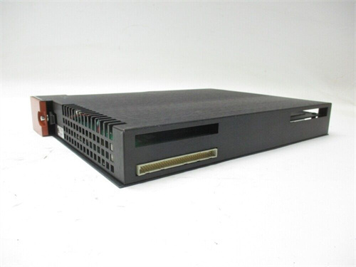
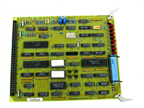
| Model | IS200TAMBH1A |
| Analog Inputs | 8 channels (4–20 mA, 0–10 V, ±10 V selectable) |
| Discrete Inputs | 16 channels (24/48/125 VDC, auto-ranging, opto-isolated) |
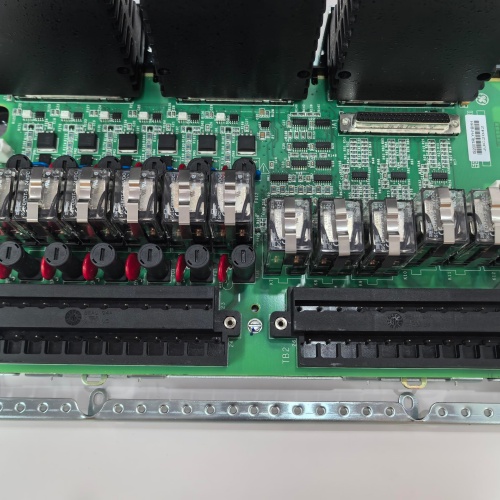
| Discrete Outputs | 8 channels (relay outputs, Form C, 5A @ 250 VAC / 30 VDC) |
| ADC Resolution | 16-bit SAR (analog inputs) |
| Analog Accuracy | ±0.1% of full scale |
| Isolation | 1500 VAC (field-to-system) |
| Operating Temperature | –30°C to +65°C |
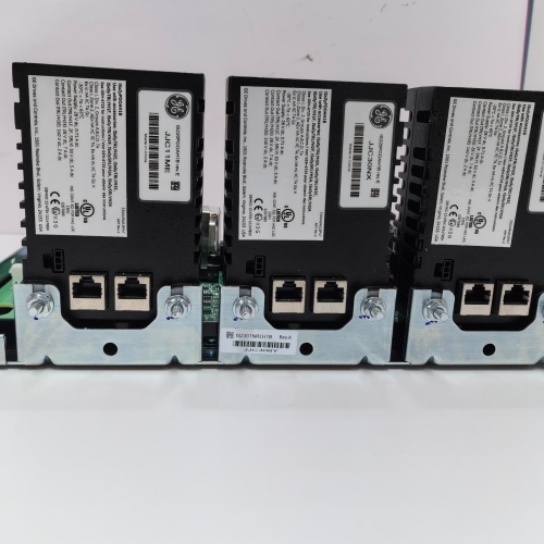
| Mounting | VME rack-mount terminal board with front-panel I/O connectors |
| Backplane Interface | VME64 (A24/A32, D16/D32) |
| Status Indication | Per-channel LEDs (analog active, discrete status, output state, fault summary) |
| Diagnostics | Open-circuit, short-circuit, over/under-range, contact monitoring, relay weld detection |
Advantages & Key Features
-
Mixed Signal Integration: IS200TAMBH1A combines 8 analog inputs, 16 discrete inputs, and 8 discrete relay outputs on a single board—reducing rack space, cabling, and the need for multiple specialized I/O boards.
-
Flexible Analog Inputs: Each analog channel supports 4–20 mA, 0–10 V, or ±10 V inputs via GE ToolboxST configuration, accommodating a wide range of field sensors.
-
Wide Discrete Voltage Compatibility: Discrete inputs auto-range for 24/48/125 VDC, connecting directly to legacy plant battery systems.
-
Integrated Relay Outputs: 8 Form C relay outputs with 5A contact rating for direct actuator control—no external intermediate relays required for many applications.
-
Comprehensive Diagnostics: Per-channel open-circuit, short-circuit, over/under-range, and relay weld detection enable predictive maintenance and fault isolation.
-
Built-In Signal Conditioning: Onboard filtering, isolation, and surge protection eliminate external signal conditioning modules.
-
ToolboxST Integration: Full configuration, monitoring, and diagnostics via GE ToolboxST.
-
Drop-In Replacement: Direct replacement for earlier GE terminal assembly boards.
Application Fields
-
Gas & Steam Turbines (GE Frame 6B/7EA/9E/HA): Monitoring analog signals (pressure, temperature, position) plus discrete alarms, valve limit switches, ESD pushbuttons, and actuator control outputs.
-
Combined Cycle Plants: HRSG monitoring and control—feedwater flow (analog), drum level switches (discrete), bypass valve control (relay outputs).
-
Compressor Stations: Suction/discharge pressure monitoring, surge control permissives, and valve position feedback.
-
Auxiliary Systems: Lubrication oil monitoring, cooling water control, and generator auxiliary control.
Comparison with Competing Products
| Feature | GE IS200TAMBH1A | Competitor A (Mixed I/O Module) | Competitor B (Discrete + Analog) |
|---|---|---|---|
| Analog Inputs | 8 (4–20mA, V) | 4 (4–20mA only) | 4 (4–20mA only) |
| Discrete Inputs | 16 (24/48/125 VDC) | 8 (24 VDC only) | 8 (24 VDC only) |
| Discrete Outputs | 8 relay (5A) | 4 relay (2A) | 4 solid-state |
| Isolation | 1500 VAC | 1000 VAC | 500 VDC |
| Operating Temp | –30°C to +65°C | 0°C to 50°C | 0°C to 60°C |
Key Advantage: IS200TAMBH1A provides the most comprehensive mixed-signal integration in a single VME slot, with wide voltage compatibility, high relay contact rating, and full diagnostics—reducing cabinet space and simplifying design.
Selection Guidelines & Recommendations
-
Signal Verification: Confirm analog input types (4–20 mA, 0–10 V, ±10 V) and discrete voltage (24/48/125 VDC) for your field sensors.
-
Output Loading: Ensure relay outputs are not overloaded—5A per channel maximum, total load limited by board power rating.
-
Controller Firmware: Requires Mark VIe processor firmware v7.0 or later.
-
Spare Strategy: Keep one spare per turbine; lead times 6–10 weeks.
-
Retrofit: Direct replacement—regenerate configuration in GE ToolboxST.
Important Cautions
-
No Hot-Swap: De-energize rack before insertion/removal.
-
Analog Polarity: Observe correct polarity for 4–20 mA loops and voltage inputs.
-
Discrete Wiring Polarity: DC discrete inputs are polarity-sensitive—reverse polarity triggers fault LED.
-
Relay Contact Protection: For inductive loads, use external suppression (varistors or diodes) to protect relay contacts.
-
Grounding: Connect AGND and ISO_GND to Mark VIe system ground at single star point.
-
Shield Termination: Ground analog and discrete cable shields only at cabinet end.
-
ESD Handling: Use grounded wrist straps; field repair not possible.
-
Load Protection: Sustained analog input >30 V or >50 mA may damage input circuitry.
A-B 1756-L55M14
A-B 1756-L55
SCHNEIDER 140ESI06210
ABB SPDSI13
.jpg)

Reviews
There are no reviews yet.