
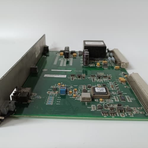
Description
Product Parameters
| Parameter | Specification |
|---|---|
| Brand / Series | GE Mark VIe Speedtronic |
| Model | IS200SFCBG1A |
| Fan Channels | 4 independently controlled DC brushless fans (12 VDC or 24 VDC compatible) |
| Control Method | PWM speed control (0–100% duty cycle) |
| Tachometer Inputs | 4 independent speed feedback channels (frequency range: 50 Hz – 500 Hz) |
| Temperature Sensors | 2 onboard NTC thermistors (chassis ambient + exhaust air) |
| Voltage Output | 12 VDC or 24 VDC (jumper-selectable) at 2.5A per channel (max total 8A) |
| Speed Control Accuracy | ±2% of setpoint |
| Fault Detection | Fan stalled, fan over-speed, fan under-speed, open-circuit, over-temperature, sensor failure |
| Alarm Outputs | 2 dedicated fault relay contacts (C-form) to the Mark VIe controller |
| Operating Temperature | –30°C to +65°C |
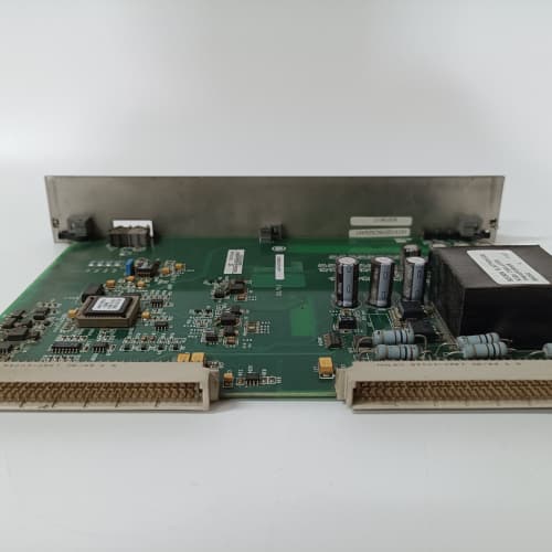
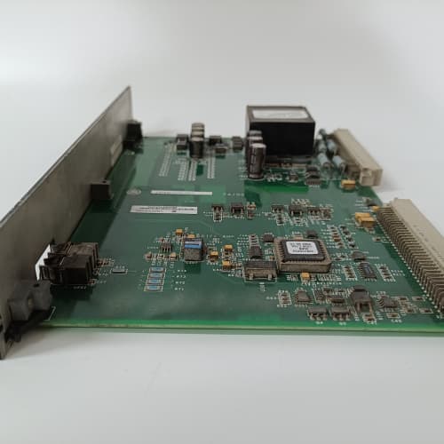
| Mounting Type | VME rack-mount board (6U form factor) with front-panel fan headers |
| Status Indication | 4 green LEDs (fan running), 4 red LEDs (fan fault), yellow over-temp alarm LED |
| Communication | VME backplane (control/status registers accessible via GE ToolboxST) |
Advantages & Key Features
-
Intelligent Thermal Management: IS200SFCBG1A continuously monitors two onboard temperature sensors and adjusts fan speeds dynamically via PWM. This closed-loop control reduces fan noise, extends fan bearing life, and minimizes dust ingress compared to constant-speed operation—a significant advantage over passive or fixed-speed cooling solutions.
-
Independent Channel Control: Each of the four fan channels on IS200SFCBG1A can be programmed individually via the Mark VIe controller. For example, fans near high-heat power supplies can run at higher speeds than those in cooler regions of the same cabinet, optimizing power consumption and airflow distribution.
-
Real-Time Tachometer Feedback: The board uses dedicated frequency inputs to monitor each fan’s actual rotational speed. If a fan falls below a programmable threshold (e.g., 70% of nominal RPM), IS200SFCBG1A generates a fault signal to the GE ToolboxST alarm system, enabling predictive maintenance before a complete fan failure causes cabinet over-temperature.
-
Comprehensive Fault Diagnostics: Detected conditions include: stalled rotor (zero tachometer pulses), over-speed (runaway due to driver failure), under-speed (bearing wear or obstruction), open-circuit (disconnected fan), and over-temperature (chassis or exhaust sensor). Each fault is latched and reported to the Mark VIe controller.
-
Relay Alarm Outputs: Two dedicated fault relays provide hardwired alarm contacts that can trigger external annunciators or emergency shutdown logic—critical for safety-certified turbine installations where software alarms alone are insufficient.
-
Drop-In Replacement Compatibility: IS200SFCBG1A is a direct replacement for earlier GE fan control boards such as the IS200SFCBH1A, with improved PWM frequency, wider voltage compatibility, and enhanced fault detection granularity, while maintaining identical mounting holes, connector pinouts, and backplane addressing.
Application Fields & Use Cases
-
Power Generation (Gas & Steam Turbines): IS200SFCBG1A is used in GE Frame 6B, 7EA, 9E, and HA-class turbine control cabinets to manage cooling fans for:
-
VME main processor chassis (e.g., IS420UCSBH1A / IS420UCSCH1A)
-
I/O terminal boards (e.g., IS200SCTLG1ABA, IS200SCTTG1AAA)
-
Power supply modules
-
High-speed data acquisition boards
-
Ethernet communication modules
-
-
Combined Cycle Plants: Deployed in HRSG control cabinets where high ambient temperatures near boilers demand continuous active cooling.
-
Oil & Gas Facilities: Used in compressor station control panels located in outdoor shelters with wide temperature swings, where IS200SFCBG1A dynamically adjusts fan speed to maintain internal cabinet temperature setpoints.
-
Marine & Offshore Platforms: Installed in turbine control enclosures where saltwater ingress prevention requires maintaining positive cabinet pressure—fan speed control is essential to balance airflow and filter loading.
-
Hydropower Plants: Used in turbine governor cabinets where reliable cooling is required in humid, enclosed environments.
Comparison with Competing Products
| Feature | GE IS200SFCBG1A (Mark VIe) | Competitor A (Schroff Fan Controller) | Competitor B (Siemens S7-1200 PWM Fan Module) | Competitor C (Phoenix Contact Fan Management) |
|---|---|---|---|---|
| Fan Channels | 4 (independent) | 2 (dependent) | 1 (requires external relays) | 3 (independent) |
| Tachometer Feedback | Yes (4 dedicated inputs) | No (open-loop only) | No (no feedback) | Yes (only 2 inputs) |
| Temperature Sensor Inputs | 2 onboard thermistors | None (external only) | 0 (requires external RTD module) | 1 onboard sensor |
| Voltage Range | 12/24 VDC jumper-selectable | 24 VDC only | 12 VDC only | 24 VDC only |
| Fault Relays | 2 dedicated C-form | 1 (limited functionality) | None | 1 (software-driven) |
| VME Backplane Integration | Yes (direct read/write via Mark VIe) | No (standalone) | No (requires PLC programming) | No (standalone) |
| Speed Accuracy | ±2% closed-loop | ±10% open-loop | ±5% open-loop | ±4% closed-loop |
| Fault Detection | Stall, under/over-speed, open-circuit, over-temp | Over-temp only | None | Stall only |
Key Advantage: IS200SFCBG1A offers superior closed-loop fan control with dedicated tachometer feedback on all four channels—a feature that competing standalone fan controllers typically reserve for only one or two channels. Its full integration with the Mark VIe VME backplane allows the GE system to log trends, predict fan end-of-life, and coordinate cooling with thermal load data from the main CPU, providing a level of smart cooling management not available in generic PLC or third-party solutions.
Selection Guidelines & Recommendations
-
Verify Fan Voltage: IS200SFCBG1A supports both 12 VDC and 24 VDC fans. Before installation, confirm the voltage rating of your existing cabinet fans and set the onboard jumper (JP1) accordingly. Incorrect voltage selection will damage the fan motors or cause under-speed faults.
-
Check Fan Power Rating: Each channel of IS200SFCBG1A can supply up to 2.5A continuous. Ensure your fans do not exceed this limit individually, and that the total combined current across all four channels does not exceed 8A. For high-power fans (e.g., >2.5A), consider splitting them across multiple boards.
-
Tachometer Signal Compatibility: The tachometer inputs on IS200SFCBG1A accept open-collector or push-pull outputs with frequency ranges of 50–500 Hz. Verify your fans provide a tach signal compatible with this range—many third-party fans use 2 pulses per revolution, which must be scaled in GE ToolboxST to display true RPM.
-
Controller Firmware Revision: Ensure your Mark VIe main processor (e.g., IS420UCSBH1A or IS420UCSCH1A) is running firmware v6.5 or later to support all diagnostic registers and the dual-temperature sensor readback. Earlier firmware versions will recognize IS200SFCBG1A only as a basic on/off controller.
-
ToolboxST Configuration: In GE ToolboxST, configure the following for each fan channel:
-
Minimum and maximum PWM duty cycle (e.g., 30% minimum to prevent stalling, 100% maximum)
-
Under-speed alarm threshold (e.g., 70% of nominal RPM)
-
Over-speed alarm threshold (e.g., 120% of nominal RPM)
-
Temperature setpoint for automatic speed adjustment
-
-
Cooling Strategy: For optimal thermal management, position one temperature sensor of IS200SFCBG1A near the air intake and the other near the exhaust. Program the board to increase fan speed when the exhaust temperature exceeds the intake by a configurable differential (e.g., 15°C), indicating reduced cooling efficiency.
-
Spare Parts: Keep at least one spare IS200SFCBG1A per turbine cabinet. Lead times for this board typically range from 4–8 weeks, as GE produces it in moderate batch runs.
-
Retrofit Consideration: When replacing older GE fan control boards (e.g., IS200SFCBH1A) with IS200SFCBG1A, note that the connector pinouts are identical, but the configuration registers in ToolboxST have changed. Export your existing configuration, create a new board instance for IS200SFCBG1A, and import the fan speed profiles manually—do not attempt to reuse old register maps.
Important Cautions
-
No Hot-Swap: IS200SFCBG1A is not hot-swappable. Always de-energize the Mark VIe rack before inserting or removing the board. Hot-swapping may cause backplane transients that corrupt the fan control registers or damage the onboard PWM drivers.
-
Fan Polarity: Double-check the polarity of fan connections to the headers on IS200SFCBG1A. Reverse polarity will not damage the board but will prevent the fan from spinning and trigger a stall fault after the startup timeout period (configurable via ToolboxST, default 5 seconds).
-
Tachometer Shielded Wiring: For reliable speed feedback, use shielded twisted-pair cables for tachometer signals, especially if fan cables exceed 1.5 meters. Connect the shield only at the IS200SFCBG1A side to a dedicated ground pin—not at both ends—to avoid ground loops that corrupt the frequency measurement.
-
Temperature Sensor Placement: The two onboard thermistors of IS200SFCBG1A are located near the top edge of the board. When installing IS200SFCBG1A in a crowded rack, ensure adjacent boards do not obstruct airflow over these sensors; blocked sensors will report artificially high temperatures and cause unnecessary fan over-speed.
-
Jumper Configuration: The voltage selection jumper (JP1) on IS200SFCBG1A must be set before powering the board. Changing the jumper while the board is energized may cause voltage transients and damage connected fans. Always de-energize the rack before changing JP1.
-
Parallel Fan Connections: Do not connect multiple fans to a single channel of IS200SFCBG1A unless the total current draw is below 2.5A and all fans have identical tachometer characteristics. Parallel fans with different tach output frequencies will cause erratic speed readings and false alarms.
-
Grounding Practice: The logic ground and fan power ground on IS200SFCBG1A are internally isolated. Connect the fan power ground return directly to the Mark VIe power supply negative terminal—do not chassis-ground the fan returns separately, as this will inject noise into the tachometer inputs.
-
ESD Handling: Although IS200SFCBG1A has ESD protection to 8 kV, always wear grounded wrist straps during handling. The PWM driver ICs and tachometer frequency counter circuits are sensitive to static discharge; field repair is not possible due to conformal coating.
С SHM62J
WOODWARD 9907-028
WESTINGHOUSE 1C31238H01


Reviews
There are no reviews yet.