
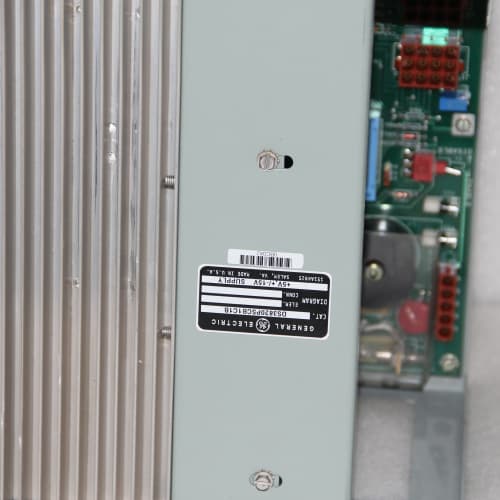
Description
Key Parameters
-
Channels: 8 digital outputs (sourcing – positive switching)
-
Output Voltage: 24 V DC nominal (18–32 V DC)
-
Output Current: 0.5 A per channel (continuous), 2 A peak (short duration)
-
Total Current: 4 A per module (all channels combined)
-
Protection: Per-channel electronic overcurrent protection (auto-restart after fault clears), short-circuit protection, thermal protection
-
Diagnostics: Open-wire detection, short-circuit detection, per-channel LED status, over-temperature alarm
-
Fail-Safe States: Software-configurable per channel (hold last state, go to ON, go to OFF) on communication loss
-
Isolation: 1500 V RMS (field-to-backplane); 500 V RMS between channels
-
Power: 24 V DC backplane power, ≤2 W (logic); external 24 V field supply required for outputs
-
Operating Temperature: –40°C to +70°C
-
Terminals: Screw-type (suffix-dependent)
Advantages
-
Electronic short-circuit protection – per-channel auto-restart protection eliminates the need for external fuses; reduces downtime and maintenance.
-
Open-wire detection – detects broken output wiring or disconnected loads; alerts operators for proactive maintenance.
-
Per-channel diagnostics – each output provides feedback on status (ON/OFF, short-circuit, open-wire, over-temperature) via the backplane.
-
Software-configurable fail-safe – define output behavior (hold, ON, OFF) on communication loss for safe system shutdown.
-
High channel density – 8 outputs in a single slot; saves rack space.
-
LED status indicators – per-channel visual indication for quick troubleshooting.
-
Hot-swappable – replace without rack power-down.
-
Optical isolation – protects backplane from field transients.
Applications
-
Solenoid control – actuating pneumatic or hydraulic valves in process control
-
Relay control – driving interposing relays for motor starters and contactors
-
Indicator lights – pilot lights and annunciator panels for operator feedback
-
Alarm annunciation – horns, beacons, and visual alarms for plant safety
-
Motor control centers (MCC) – start/stop commands for motors (via contactors)
-
Packaging machinery – output control for actuators and ejectors
-
Building automation – lighting and HVAC damper control
Competitor Comparison
| Feature | DS3820EMMA | Standard Fused Output Module | Competitor Protected Output Module |
|---|---|---|---|
| Protection | Electronic (auto-restart) | Fuse (manual replacement) | Electronic (auto-restart) |
| Open-Wire Detection | Yes | No | Optional |
| Short-Circuit Detection | Yes | No | Yes |
| Fail-Safe Configuration | Software (per channel) | Fixed (hardware) | Software (per channel) |
| Diagnostic Feedback | Full (backplane) | None | Basic |
| Maintenance Cost | Low (auto-restart) | High (fuse replacement) | Low |
| Cost | Mid | Low | High |
The DS3820EMMA is the intelligent protected output module. Compared to standard fused output modules, it eliminates manual fuse replacement (auto-restart), provides diagnostic feedback, and offers software-configurable fail-safe states – significantly reducing downtime and maintenance costs. Against competitor protected output modules, the DS3820EMMA offers superior diagnostics (open-wire detection) and per-channel fail-safe configuration at a lower cost. For critical control applications where output faults must be identified and managed promptly, the DS3820EMMA is the most cost-effective solution.
Selection Tips
-
Choose DS3820EMMA when you need protected outputs with diagnostic feedback – ideal for critical control loops and remote installations.
-
Ideal for applications where manual fuse replacement is impractical or where fault diagnosis is essential.
-
Verify the output current requirement – the DS3820EMMA provides 0.5 A per channel; use external relays for higher loads.
-
Consider the fail-safe behavior – configure each channel for the safe state on communication loss.
-
Not suitable for AC loads – use dedicated AC output modules.
-
Ensure your PLC/DCS can read and process diagnostic data from the DS3820EMMA.
Precautions
-
Output current: Do not exceed 0.5 A per channel continuously. The auto-restart protection will trip on overload – repeated trips may reduce the module’s lifespan.
-
Inductive loads: Use external flyback diodes or surge suppressors for inductive loads (solenoids, relays) to prevent back-EMF damage.
-
Wiring: Use appropriately sized wiring for 0.5 A output current. Keep output wiring separate from sensitive input signals to avoid crosstalk.
-
Power: Requires external 24 V field supply for outputs – ensure supply capacity meets total current demand (up to 4 A per module).
-
Fail-safe testing: Test fail-safe behavior during commissioning – confirm outputs go to the desired state on communication loss.
-
Open-wire detection: Requires a minimum load current – very high-impedance loads may not trigger open-wire detection.
-
Grounding: Maintain proper grounding to avoid ground loops.
-
Spare: Keep one spare DS3820EMMA for critical output applications – the integrated protection features may have longer lead times.
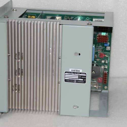
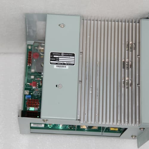
A-B 20DC460N0ENNBNBNE
A-B 1747-BA
GE ACC-5595-208


Reviews
There are no reviews yet.