
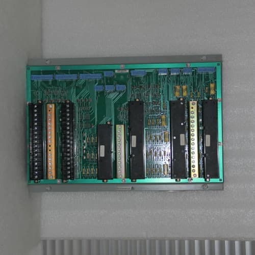
Description
Key Parameters
Power Supply Section:
-
Power Outputs: Multiple regulated DC outputs (+5V, ±15V, +24V, and configurable auxiliary outputs)
-
Excitation Outputs: Adjustable excitation for transducers (e.g., 3V, 5V, 10V DC, or 4–20mA loop power)
-
Output Accuracy: ±0.05% regulation
-
Ripple/Noise: <5 mV peak-to-peak
-
Diagnostics: LED status indicators for each output, over-voltage/over-current protection, thermal shutdown, output voltage monitoring
Relay Output Section:
-
Output Channels: 16 or 24 Form-C (SPDT) relay outputs (depending on configuration)
-
Relay Type: Dual-coil latching relays (redundant coil drive – enhanced reliability)
-
Contact Rating: 5A at 250V AC / 30V DC (resistive load)
-
Output Coil: 24V DC (from backplane or external supply) – dual coils for each relay
-
Diagnostics: Per-channel LED status, enhanced coil fault detection (both coils) , contact weld detection, fuse status indication, self-test on power-up
-
Response Time: 10–15ms (relay operate time)
Common Section:
-
Isolation: 2500V RMS channel-to-backplane
-
Field Wiring: Integrated terminal blocks for direct field wiring
-
Temp Range: –40°C to +85°C (extended)
-
Power Supply: +5V (logic), +24V (relay coils and field power) from backplane or external supply (higher current draw due to dual coils)
-
Physical: 6U VME single-slot board
-
Key Features: Integrated power supply + dual-coil relay outputs, Form-C contacts, 5A contact rating, redundant coil drive, contact weld detection, extended temp range, high isolation
Advantages
-
Integrated power + redundant relay outputs – the DS3815PRDB combines sensor excitation and high-current dual-coil relay outputs in a single module, reducing board count and simplifying system architecture.
-
Dual-coil reliability – uses dual-coil latching relays, providing redundant coil drive for critical circuits. If one coil fails, the other can still operate the relay.
-
Contact weld detection – the General Electric DS3815PRDB monitors contact status and detects welded contacts, providing early warning of relay failure.
-
Space-saving – replaces up to three separate boards (power supply, relay output, and excitation supply) with one module.
-
Stable sensor excitation – provides clean, regulated power for speed pickups, proximity probes, pressure transmitters, and other transducers.
-
Adjustable excitation – allows matching excitation levels to specific sensor requirements.
-
High-current relay outputs – 5A contact rating handles larger loads than solid-state outputs.
-
Form-C contacts – provides both NO and NC outputs for fail-safe wiring.
-
Enhanced diagnostics – coil fault detection (both coils), contact weld detection, and self-test on power-up for comprehensive health monitoring.
-
Extended temperature range – operates from –40°C to +85°C for harsh environments.
-
Comprehensive protection – over-voltage, over-current, and thermal protection safeguard the board and connected field devices.
-
High isolation – 2500V RMS isolation protects the backplane from field-side faults.
-
Drop-in compatible – works with all Mark IV backplanes and processor configurations.
Applications
-
Critical turbine trip and shutdown circuits – the DS3815PRDB drives critical trip solenoids with redundant coil drive for enhanced reliability.
-
Safety-critical alarm circuits – used for overspeed, high temperature, and low lube oil pressure alarms where relay failure is not acceptable.
-
Alarm annunciation – drives panel lamps, horns, and DCS alarm inputs with high-current relay outputs.
-
Motor and valve control – controls auxiliary motors, solenoid valves, and isolation valves.
-
Sensor excitation with relay control – powers field sensors while simultaneously providing relay outputs for discrete control.
-
Offshore and harsh environments – extended temperature range makes it suitable for demanding applications.
-
Retrofits – replaces separate power supply and relay output boards with a single, integrated, high-reliability solution.
vs Competitors & Separate Boards
| Feature | DS3815PRDB | DS3815PRBA (Single-Coil) | DS3800XPEN + DS3810RAMC | Generic VME Combo Board |
|---|---|---|---|---|
| Power outputs | Yes | Yes | Yes + No | Varies |
| Relay outputs | 16–24 (5A, dual-coil) | 16–24 (5A, single-coil) | 0 + 24–32 (dual-coil) | 8–16 |
| Dual-coil redundancy | Yes | No | Yes | Rarely |
| Contact weld detection | Yes | No | Yes | Rarely |
| Coil fault detection | Yes (both coils) | Yes (single) | Yes (both) | Rarely |
| Board count | 1 | 1 | 2 | 1 |
| Extended temp range | –40°C to +85°C | –40°C to +85°C | –40°C to +85°C | 0°C to +60°C |
Selection Tips
-
Redundant relay outputs + power – choose the DS3815PRDB for safety-critical applications requiring redundant coil drive, contact weld detection, and sensor excitation in a single module.
-
Slot-limited installations – the General Electric DS3815PRDB reduces board count compared to separate power supply and dual-coil relay boards.
-
Fail-safe wiring – Form-C contacts provide both NO and NC outputs, essential for critical trip circuits.
-
Sensor compatibility – verify that the excitation voltage and current requirements of your sensors match the DS3815PRDB outputs.
-
Load verification – ensure the 5A contact rating is sufficient for your loads; use external contactors for higher currents.
-
Harsh environments – the extended temperature range makes it suitable for offshore, desert, or unheated cabinet installations.
-
Power loading – the DS3815PRDB draws more current due to dual coils. Calculate total draw and verify backplane power capacity.
-
Spare strategy – keep one DS3815PRDB per 5–8 installed units, especially in critical safety applications.
-
Wiring planning – plan field wiring terminations carefully to leverage the integrated terminal blocks efficiently.
Critical Precautions
-
Power supply loading – the DS3815PRDB has higher current draw due to dual coils. Do not exceed backplane power ratings.
-
Output voltage selection – verify that the DS3815PRDB output voltages are correctly configured before connecting sensors. Incorrect voltage can damage sensors.
-
Output over-current – do not exceed the relay contact rating (5A). Overloading can weld contacts or cause overheating.
-
Dual-coil operation – ensure the dual-coil drive logic is correctly configured. Incorrect coil drive can cause relay switching failures.
-
Inductive loads – for DC solenoid and relay coil loads, install a flyback diode across the load to prevent voltage spikes from damaging the General Electric DS3815PRDB relay contacts or control circuitry.
-
Contact weld detection – if contact weld detection is triggered, verify the relay contact status and replace the DS3815PRDB if a contact is welded.
-
Field wiring – use appropriate wire gauge for field connections. Loose connections can cause intermittent faults or overheating.
-
Fuse replacement – if a fuse status indicator shows a fault, verify the field wiring and load before replacing the fuse. Use only the specified fuse rating.
-
Relay contact wear – for high-cycle applications, consider derating the contacts or using an external interposing relay.
-
Cable shielding – use shielded cables for sensor and output wiring. Ground the shield only at the DS3815PRDB end.
-
Ground loops – use single-point grounding for all sensors and outputs connected to the DS3815PRDB.
-
Heat dissipation – ensure adequate cabinet cooling (>250 CFM); the DS3815PRDB generates significant heat under full load.
-
Self-test – allow the DS3815PRDB to complete its power-up self-test (~2 seconds) before relying on outputs.
-
Calibration intervals – schedule periodic calibration verification (every 6–12 months).
-
Hot-swap – never insert or remove the DS3815PRDB while the rack is powered.
-
ESD handling – always use a grounded wrist strap.
-
Storage – store spare DS3815PRDB boards in anti-static bags in a dry, temperature-controlled environment.
SCHNEIDER GV3A01
A-B 1786-XT
A-B 1746-NI8




Reviews
There are no reviews yet.