
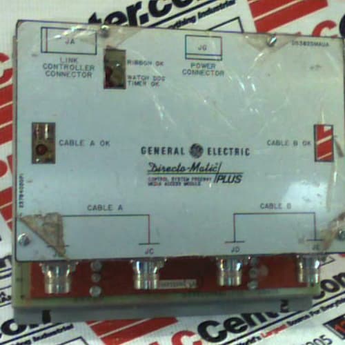
Description
Key Parameters
Power Supply Section:
-
Power Outputs: Multiple regulated DC outputs (+5V, ±15V, +24V, and configurable auxiliary outputs)
-
Excitation Outputs: Adjustable excitation for transducers (e.g., 3V, 5V, 10V DC, or 4–20mA loop power)
-
Output Accuracy: ±0.05% regulation
-
Ripple/Noise: <5 mV peak-to-peak
-
Diagnostics: LED status indicators for each output, over-voltage/over-current protection, thermal shutdown, output voltage monitoring
Frequency Counter Section:
-
Frequency Input Channels: 4 independent counter/frequency channels
-
Input Types: Magnetic pickup, proximity, TTL (5V), or 24V DC (jumper-selectable per channel)
-
Maximum Input Frequency: 100 kHz per channel
-
Counter Resolution: 32-bit (up/down counter)
-
Encoder Support: Incremental (A/B/Z) with quadrature decoding (x1, x2, x4)
-
Speed Measurement: Calculates RPM with <0.01% accuracy
-
Measurement Method: Pulse counting or period-averaging (software-selectable)
-
Diagnostics: Per-channel LED status, input signal loss detection, frequency threshold alarms
Serial Communication Section:
-
Communication Ports: 1 or 2 independent serial ports
-
Protocols Supported: Modbus RTU (Master/Slave), GE Mark IV proprietary protocol, ASCII
-
Physical Interfaces: RS-232, RS-422, RS-485 (jumper-selectable per port)
-
Baud Rates: 300 to 115200 bps (software-selectable)
-
Function: Transmits frequency and speed data to external systems; receives setpoints
-
Diagnostics: Per-port LED status (TX/RX/error), communication error counters
Common Section:
-
Isolation: 2500V RMS channel-to-backplane
-
Temp Range: –40°C to +85°C (extended)
-
Power Supply: +5V (logic), +24V/48V (field power) from backplane or external supply
-
Physical: 6U VME single-slot board
-
Key Features: Integrated power supply + frequency counter + serial communication, 32-bit counter, quadrature decoding, extended temp range, high isolation
Advantages
-
Integrated frequency measurement + communication + power – the DS3815PFZC combines sensor excitation, high-speed frequency counting, and serial communication in a single module, reducing board count and simplifying system architecture.
-
Space-saving – replaces up to four separate boards (power supply, frequency counter, serial communication, and excitation supply) with one module.
-
Stable sensor excitation – provides clean, regulated power for speed pickups, proximity probes, and other transducers.
-
Adjustable excitation – allows matching excitation levels to specific sensor requirements.
-
High-speed counting – the General Electric DS3815PFZC accepts frequencies up to 100 kHz, suitable for high-speed turbine speed pickups and flowmeter pulse inputs.
-
Encoder support – quadrature decoding (x1, x2, x4) provides precise position and direction information.
-
Built-in speed calculation – calculates RPM directly from input frequency, reducing main processor load.
-
Serial connectivity – transmits frequency and speed data to DCS, SCADA, and HMIs via Modbus RTU or GE proprietary protocols.
-
Input signal diagnostics – loss-of-signal detection and frequency threshold alarms provide early warning of sensor or wiring issues.
-
Extended temperature range – operates from –40°C to +85°C for harsh environments.
-
Comprehensive protection – over-voltage, over-current, and thermal protection safeguard the board and connected field devices.
-
High isolation – 2500V RMS isolation protects the backplane from field-side faults.
-
Drop-in compatible – works with all Mark IV backplanes and processor configurations.
Applications
-
Turbine speed monitoring with DCS integration – the DS3815PFZC measures turbine speed and transmits data to plant-wide DCS via Modbus.
-
Overspeed protection with remote monitoring – measures frequency from speed pickups with loss-of-signal detection and communicates speed data to SCADA systems.
-
Flow measurement with data reporting – counts pulses from turbine flowmeters and reports flow rates to external monitoring systems.
-
Encoder feedback with external communication – reads quadrature encoder signals for valve position or shaft timing and transmits position data.
-
Remote speed control – receives speed setpoints via serial communication and provides measured speed feedback.
-
Offshore and harsh environments – extended temperature range makes it suitable for demanding applications.
-
Retrofits – replaces separate power, frequency counter, and communication boards with a single, integrated solution.
vs Competitors & Separate Boards
| Feature | DS3815PFZC | DS3815PFCA (Counter only) | DS3800XPEN + DS3800XCIA + DS3800XJBA | Generic VME Combo Board |
|---|---|---|---|---|
| Power outputs | Yes | Yes | Yes + No + No | Varies |
| Frequency inputs | 4 | 4 | 0 + 4 + 0 | 2–4 |
| Serial communication | Yes | No | 0 + 0 + Yes | Rarely |
| Quadrature decoding | Yes | Yes | Yes (XCIA) | Rarely |
| Built-in speed calculation | Yes | Yes | Yes (XCIA) | No |
| Board count | 1 | 1 | 3 | 1 |
| Extended temp range | –40°C to +85°C | –40°C to +85°C | –40°C to +85°C | 0°C to +60°C |
| Isolation | 2500V | 2500V | 2500V | 500–1500V |
Selection Tips
-
Frequency measurement + communication + power – choose the DS3815PFZC when you need sensor excitation, frequency measurement, and serial communication in a single module.
-
Slot-limited installations – the General Electric DS3815PFZC reduces board count compared to separate power, frequency counter, and communication boards.
-
DCS/SCADA integration – if you need to transmit speed, flow, or position data to a plant-wide control system, the DS3815PFZC provides built-in serial communication.
-
Encoder feedback – the quadrature decoding support is useful for valve position or shaft timing applications.
-
Sensor compatibility – verify that the excitation voltage and current requirements of your sensors match the DS3815PFZC outputs.
-
Protocol requirements – confirm that your external systems support Modbus RTU or GE proprietary protocols.
-
Frequency input type – configure each of the 4 frequency inputs for magnetic, proximity, TTL, or 24V sensors as required.
-
Harsh environments – the extended temperature range makes it suitable for offshore, desert, or unheated cabinet installations.
-
Power loading – calculate the total current draw of all connected sensors and ensure it does not exceed the DS3815PFZC total power rating.
-
Spare strategy – keep one DS3815PFZC per 5–8 installed units, especially in critical speed monitoring and communication applications.
-
Calibration – periodically verify output voltages, frequency measurement accuracy, and communication integrity using precision instruments.
Critical Precautions
-
Power supply loading – do not exceed the DS3815PFZC current rating for any output. Overloading can cause voltage drop, overheating, or shutdown.
-
Output voltage selection – verify that the DS3815PFZC output voltages are correctly configured before connecting sensors. Incorrect voltage can damage sensors.
-
Frequency input voltage limits – never apply voltage above 30V to the frequency inputs; magnetic pickups can generate high voltages at high speeds – use appropriate attenuation.
-
Serial interface selection – ensure the serial port jumpers are correctly set for RS-232, RS-422, or RS-485 before connecting field devices. Incorrect settings can damage the board or connected devices.
-
Cable length limits – RS-232: <15 m; RS-422/485: <1200 m.
-
Grounding – for RS-485 multi-drop networks, ensure proper termination resistors (120Ω) are installed at each end of the bus.
-
Cable shielding – use shielded twisted-pair cables for frequency inputs and serial connections. Ground the shield only at the General Electric DS3815PFZC end to prevent ground loops.
-
Ground loops – use single-point grounding for all sensors and communication devices connected to the DS3815PFZC to avoid ground-loop noise.
-
Sensor compatibility – verify that the DS3815PFZC input impedance and threshold levels match your specific frequency sensors.
-
Thermal considerations – ensure adequate cabinet cooling (>200 CFM); the DS3815PFZC can generate significant heat under full load.
-
Self-test – allow the DS3815PFZC to complete its power-up self-test (~2 seconds) before relying on measurements or communication.
-
Calibration intervals – schedule periodic calibration verification (every 6–12 months) to maintain accuracy.
-
Hot-swap – never insert or remove the DS3815PFZC while the rack is powered; this can cause voltage spikes or component damage.
-
ESD handling – always use a grounded wrist strap; power, precision frequency, and communication components are ESD-sensitive.
-
Storage – store spare DS3815PFZC boards in anti-static bags in a dry, temperature-controlled environment.
A-B 100-KFA20E
SCHNEIDER 140XTS00200
A-B 1786-XT
.jpg)


Reviews
There are no reviews yet.