
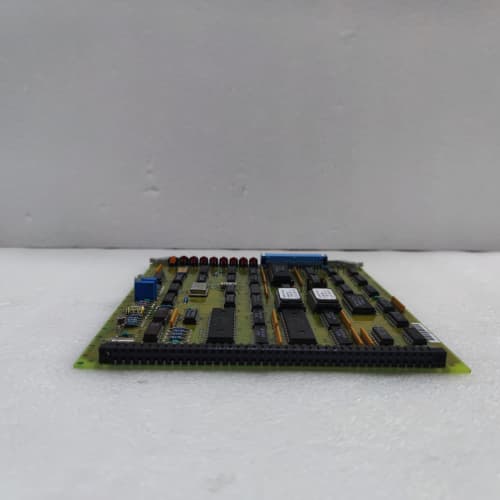
Description
Key Parameters
-
Output Channels: 8 or 16 independent digital outputs (depending on configuration)
-
Output Type: High-side or low-side solid-state drivers (jumper-selectable)
-
Output Voltage: 24V DC or 48V DC (field-selectable)
-
Output Current: 2A per channel (continuous), 4A peak (short duration)
-
Load Monitoring: Per-channel current sensing with improved accuracy (1A1A) for load fault detection (open circuit, short circuit, overload)
-
Isolation: 2500V RMS channel-to-backplane (enhanced)
-
Diagnostics: Per-channel LED status, load fault indication, over-temperature protection, fault feedback to processor, enhanced fault logging (firmware 1A1A) , self-test on power-up, signal integrity monitoring
-
Response Time: <2ms (turn-on/turn-off)
-
Temp Range: –40°C to +85°C (extended)
-
Power Supply: +5V (logic), +24V/48V (field power) from backplane or external supply
-
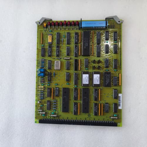
Physical: 6U VME single-slot board
-
Key Features: High-current outputs (2A), enhanced load monitoring, short-circuit protection, per-channel fault feedback, self-test, firmware rev 1A1A
Advantages
-
High-current capability – the DS3810CLCB1A1A provides 2A continuous output current per channel, enabling direct control of larger loads without external interposing relays.
-
Enhanced load monitoring – improved current sensing accuracy (firmware 1A1A) provides more precise detection of open circuits, short circuits, and overloads.
-
Solid-state outputs – no mechanical contacts to wear out, providing faster switching and longer service life than relay-based outputs.
-
Enhanced diagnostics – the 1A1A firmware provides improved fault logging, self-test on power-up, and signal integrity monitoring for predictive maintenance.
-
Comprehensive protection – short-circuit, over-current, and thermal protection on each channel safeguard the General Electric DS3810CLCB1A1A and connected field devices.
-
Fault feedback – each channel provides load status feedback to the processor, enabling rapid troubleshooting.
-
Field-configurable – jumper-selectable for high-side or low-side output and 24V or 48V operation.
-
High isolation – 2500V RMS isolation protects the backplane and processor from field-side faults.
-
Extended temperature range – operates from –40°C to +85°C for harsh environments.
-
Drop-in compatible – works with all Mark IV backplanes and processor configurations.
Applications
-
Large solenoid valve control – the General Electric DS3810CLCB1A1A drives large fuel shut-off valves, steam dump valves, and isolation valves requiring higher current.
-
Motor contactor control – directly drives contactor coils for pumps, fans, and cooling systems.
-
Heater control – controls electric heaters for lube oil, fuel gas, or other process heating applications.
-
Load monitoring applications – provides precise real-time load status for critical circuits where open-circuit or short-circuit detection is essential.
-
Offshore and harsh environments – extended temperature range and high reliability make it suitable for demanding applications.
-
Retrofits – replaces older high-current output boards with enhanced diagnostics.
vs Competitors & Previous Variants
| Feature | DS3810CLCB1A1A | Standard DS3810CLCB | DS38080HRDB | Generic VME High-Current Board |
|---|---|---|---|---|
| Output current | 2A | 2A | 0.5A | 1–2A |
| Load monitoring accuracy | Enhanced (1A1A) | Standard | No | Rarely |
| Self-test on power-up | Yes (1A1A) | No | No | No |
| Fault logging | Enhanced (1A1A) | Standard | Standard | No |
| Signal integrity monitoring | Yes | No | No | No |
| Isolation | 2500V | 2500V | 2500V | 500–1500V |
| Extended temp range | –40°C to +85°C | –40°C to +85°C | –40°C to +85°C | 0°C to +60°C |
| Response time | <2ms | <2ms | <1ms | 1–5ms |
| Firmware revision | 1A1A | Varies | Varies | N/A |
Selection Tips
-
High-current + advanced diagnostics – choose the DS3810CLCB1A1A when your field devices require up to 2A continuous current and you need enhanced load monitoring and diagnostics.
-
Critical load monitoring – the improved current sensing accuracy of the General Electric DS3810CLCB1A1A is ideal for critical circuits where precise open-circuit or short-circuit detection is essential for safety or diagnostics.
-
Predictive maintenance – the self-test and enhanced fault logging of the 1A1A firmware support proactive maintenance programs.
-
Reliability requirements – the solid-state design eliminates mechanical wear, making it suitable for high-cycle applications.
-
Field voltage matching – verify that your field devices operate at 24V or 48V DC, and configure the DS3810CLCB1A1A jumpers accordingly.
-
Firmware compatibility – confirm your Mark IV main processor firmware supports the enhanced features of the DS3810CLCB1A1A.
-
Spare strategy – keep one DS3810CLCB1A1A per 5–8 installed units, especially in critical applications with high-current loads.
-
Pre-installation testing – verify output functionality and load monitoring using the on-board diagnostic LEDs and processor feedback.
Critical Precautions
-
Output current limits – do not exceed 2A continuous per channel on the DS3810CLCB1A1A. Overloading can trigger thermal shutdown or damage the output stage.
-
Inductive loads – for solenoid and relay coil loads, install a flyback diode (for DC loads) across the load to prevent voltage spikes that can damage the General Electric DS3810CLCB1A1A output stage.
-
Field voltage selection – ensure the DS3810CLCB1A1A jumpers are correctly set for 24V or 48V operation before applying field power. Incorrect settings can damage the outputs.
-
High-side vs low-side – configure the jumper for high-side or low-side output to match your field device wiring; incorrect configuration can cause malfunction or damage.
-
Wiring polarity – observe correct polarity when connecting field devices to the DS3810CLCB1A1A outputs; reversed polarity can cause malfunction or damage.
-
Load monitoring calibration – verify the current sensing thresholds of the DS3810CLCB1A1A against your actual load currents to ensure accurate fault detection.
-
Self-test – allow the DS3810CLCB1A1A to complete its power-up self-test (~2 seconds) before relying on outputs or load monitoring.
-
Cable sizing – use appropriately sized cables for high-current outputs to prevent voltage drop and overheating of the DS3810CLCB1A1A terminal connections.
-
Heat dissipation – ensure adequate cabinet cooling; the DS3810CLCB1A1A generates significant heat under full load. Derating may apply at high temperatures; consult the technical manual.
-
Fault handling – if a load fault is reported, verify the field wiring and load before resetting or replacing the DS3810CLCB1A1A.
-
Hot-swap – never insert or remove the DS3810CLCB1A1A while the rack is powered; this can cause bus errors or damage.
-
ESD handling – always use a grounded wrist strap when handling the DS3810CLCB1A1A; CMOS and power components are ESD-sensitive.
-
Storage – store spare DS3810CLCB1A1A boards in anti-static bags in a dry, temperature-controlled environment.
A-B 1769-ECR
DIL M12-10C(220-230V50HZ)
Panasonic BR-2/3AGCT4A
.jpg)


Reviews
There are no reviews yet.