
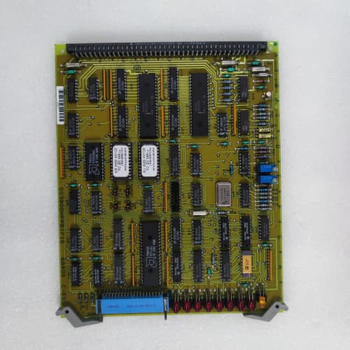
Description
Key Parameters
-
Bus Standard: VMEbus (IEEE 1014-1987)
-
Addressing: 24-bit address bus, 16-bit data bus (A24/D16)
-
Slot Count: 21 slots (standard Mark IV chassis configuration)
-
Bus Speed: 10 MHz
-
Power Distribution: +5V (50A), +12V (10A), –12V (5A), +24V (15A) from external power supplies
-
Connector Type: 96-pin DIN 41612 (3-row) per slot
-
Diagnostics: Power LED, bus activity LED, test points for monitoring voltages and clock signals
-
Protection: Fused power inputs, over-current protection per slot
-
Temp Range: –30°C to +70°C
-
Physical: 6U VME backplane, 21-slot chassis mount
Advantages
-
High integrity bus – the DS3800VCB provides clean, low-noise signal paths with controlled impedance and proper termination, ensuring error-free communication between Mark IV boards.
-
Robust power distribution – capable of delivering high currents across multiple slots with minimal voltage drop, supporting power-hungry boards like the DS3800NVOC and DS3800NVRC series.
-
Diagnostic visibility – test points on the General Electric DS3800VCB allow technicians to monitor bus signals and power rails without disconnecting boards.
-
Fused protection – each power rail has replaceable fuses to protect against shorts or over-current events.
-
Drop-in replacement – the DS3800VCB is a direct replacement for original Mark IV backplanes, maintaining the same slot mapping and pinout.
-
Long service life – built with high-grade FR4 material and gold-plated connectors rated for >500 insertion cycles.
Applications
-
Mark IV turbine control racks – provides the physical and electrical foundation for all Mark IV control systems in gas and steam turbine installations.
-
Retrofit projects – the DS3800VCB is used to replace aging or damaged backplanes while retaining existing Mark IV boards.
-
Spare chassis assembly – used to build complete spare Mark IV racks for rapid swap-out during maintenance or emergencies.
-
System upgrades – supports integration of newer Mark IV board variants while maintaining bus compatibility.
vs Competitors & Related Products
| Feature | DS3800VCB | Generic VME Backplane |
|---|---|---|
| Native Mark IV compatibility | Yes (exact slot pinout) | No (requires adapter) |
| Slot count | 21 | 21 (typical) |
| Power rating | 50A @ +5V | 20–30A @ +5V |
| Slot protection | Fused per rail | Usually none |
| Test points | Yes (voltage/bus signals) | Rarely |
| Temp range | –30°C to +70°C | 0°C to +60°C |
| Connector rating | >500 insertion cycles | 200–300 cycles |
| Gold-plated connectors | Yes (full-length) | Partial or standard |
Selection Tips
-
Chassis compatibility – verify that your Mark IV chassis is the standard 21-slot configuration; the DS3800VCB is designed specifically for this form factor.
-
Slot mapping – before installing the General Electric DS3800VCB, confirm the required slot assignments for each board type (processor, I/O, memory, etc.) based on your system documentation.
-
Power supply verification – ensure your external power supplies meet the current requirements of all boards installed; the DS3800VCB distributes power but does not regulate it.
-
Connector inspection – inspect all 96-pin connectors on the DS3800VCB for bent pins or corrosion before installation; damaged connectors can cause intermittent faults.
-
Spare strategy – keep one DS3800VCB per facility (or per 5 racks) as a spare; backplane failures are rare but catastrophic if they occur.
Critical Precautions
-
Power de-energisation – always power down the rack completely before installing, removing, or inspecting the DS3800VCB. Live backplane work is dangerous and can damage boards.
-
Fuse replacement – use only the specified fuse ratings (as marked on the General Electric DS3800VCB) when replacing fuses; higher-rated fuses can lead to PCB damage.
-
Bus termination – ensure that proper termination resistors are installed on the DS3800VCB (near the end slots) to prevent signal reflection on the VMEbus.
-
Physical alignment – when installing boards, align them carefully with the DS3800VCB connectors; forced insertion at an angle can damage pins or cause shorts.
-
Cleanliness – keep the DS3800VCB clean and free of dust, which can cause arcing or signal degradation. Use only approved anti-static cleaning methods.
-
Grounding – ensure the chassis ground is properly connected to the DS3800VCB mounting points; floating grounds can cause bus errors.
-
Battery-backed boards – when removing the DS3800VCB, note that boards with batteries (e.g., DS3800NVMB, DS3800TIMC) will lose data if their batteries are depleted; plan accordingly.
-
Hot-swap – hot-swapping is strictly prohibited for all Mark IV boards on the DS3800VCB; always power down the rack before inserting or removing any board.
Schneider A9F19363
A-B 1747-BA
SIEMENS FDM181

Reviews
There are no reviews yet.