
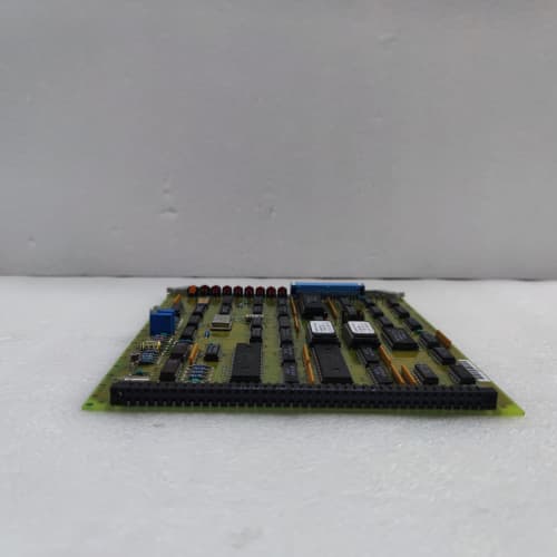
Description
Key Parameters
-
Timers: 8 independent 32-bit timers (software-configurable)
-
Timer Resolution: 1ms, 10ms, 100ms, or 1s (jumper-selectable per timer)
-
Counters: 4 independent 32-bit up/down counters
-
Counter Input: Accepts pulse signals up to 50kHz (TTL or 24V DC)
-
Outputs: 8 dedicated timer/counter output channels (open-collector, 24V DC, 0.5A)
-
Accuracy: ±0.01% over full temperature range
-
Diagnostics: LED status per timer/counter, watchdog timer, battery-backed counter retention
-
Battery Backup: Lithium 3.6V for counter value retention during power loss
-
Temp Range: –30°C to +70°C
-
Power Supply: +5V (logic), +24V (outputs) from backplane
-
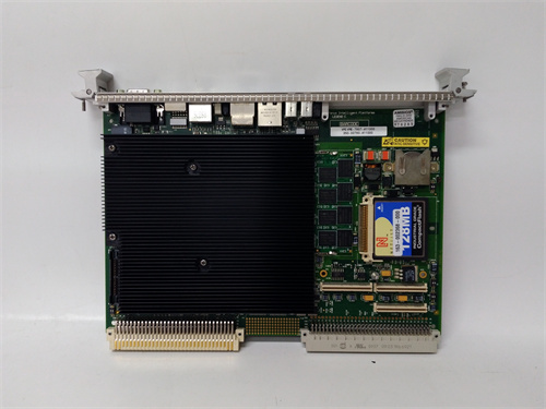
Physical: 6U VME single-slot board
Advantages
-
Hardware-based timing – the DS3800TIMC provides sub-millisecond accuracy that cannot be achieved by software timers running on the main processor.
-
Independent operation – timers and counters continue functioning even if the main processor communication is disrupted, ensuring critical time-based trips remain active.
-
Flexible configuration – each timer can be configured for one-shot, retriggerable, or free-running modes, accommodating various turbine logic requirements.
-
Counter retention – battery backup preserves run-time counters (e.g., turbine operating hours, starts count) through power cycles.
-
High-speed counting – accepts up to 50kHz pulse inputs for speed or flow measurement applications.
-
Drop-in compatible – works with all Mark IV backplanes and processor configurations.
Applications
-
Turbine purge timing – ensures proper purge duration before ignition (critical for safety).
-
Ignition and warm-up delays – controls flame stabilisation time and warm-up ramp rates.
-
Run-time accumulation – tracks turbine operating hours, starts, and trips for maintenance scheduling.
-
Speed measurement – counts pulses from magnetic pickups for speed monitoring (used with overspeed protection logic).
-
Flow totalization – accumulates pulse outputs from turbine flow meters for fuel consumption tracking.
-
Cycle timing – controls periodic functions such as valve stroke tests and bearing oil flushing intervals.
vs Competitors & Related Variants
| Feature | DS3800TIMC | Generic VME Timer Board |
|---|---|---|
| Native Mark IV firmware support | Yes (proprietary mapping) | No (requires custom coding) |
| Timers | 8 (configurable modes) | 2–4 typical |
| Timer resolution | 1ms minimum | 10ms typical |
| Counters | 4 (up/down, 50kHz) | 2 (usually up-only, <10kHz) |
| Battery-backed counters | Yes | Rarely |
| Outputs per timer | Yes (individual) | Shared or none |
| Watchdog timer | Yes (hardware) | Software-only |
| Temp range | –30°C to +70°C | 0°C to +60°C |
Selection Tips
-
Timer mode selection – verify the required mode (one-shot, retriggerable, or free-running) for each timing function before installing the General Electric DS3800TIMC.
-
Resolution setting – select the appropriate resolution (1ms, 10ms, 100ms, or 1s) via jumpers for each timer; higher resolution consumes more backplane bandwidth.
-
Counter input type – confirm the pulse source matches the DS3800TIMC input requirements (TTL 5V or 24V DC); use external signal conditioners if necessary.
-
Battery check – verify the 3.6V lithium battery voltage (should be >3.0V) before commissioning; replace every 5 years.
-
Spare strategy – keep one DS3800TIMC per 8–10 installed units; timing boards are critical for startup sequences and should be available for immediate replacement.
Critical Precautions
-
Battery replacement – power down the rack before changing the battery on the DS3800TIMC; observe correct polarity. If the battery is disconnected while powered, counter values may be corrupted.
-
Input over-voltage – never apply voltage above 30V to the DS3800TIMC counter inputs; this can damage the input optocouplers.
-
Output short – do not short the open-collector outputs to ground or positive supply; this can damage the output transistors of the General Electric DS3800TIMC.
-
Timer accuracy – for critical timing functions (e.g., overspeed trip delays), verify accuracy at the operating temperature using an external oscilloscope; temperature drift is minimal but should be confirmed during commissioning.
-
Jumper documentation – record the jumper settings for each DS3800TIMC in your facility; lost jumper configurations can be difficult to reconstruct.
-
Hot-swap – never insert or remove the DS3800TIMC while the rack is powered; this can cause timer drift or backplane damage.
-
Grounding – use shielded cables for pulse inputs to the DS3800TIMC; grounding the shield only at the board end prevents noise pickup.
-
Humidity – store spare DS3800TIMC boards in anti-static bags in a dry environment; high humidity can affect the high-impedance input circuitry.
A-B 1756-TBNH
A-B 1756-TBCH
A-B 193-KB40

Reviews
There are no reviews yet.