
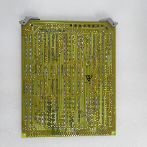
Description
Key Technical Parameters
| Parameter | Specification |
|---|---|
| Manufacturer | General Electric (GE) |
| Series | Mark V (Speedtronic) |
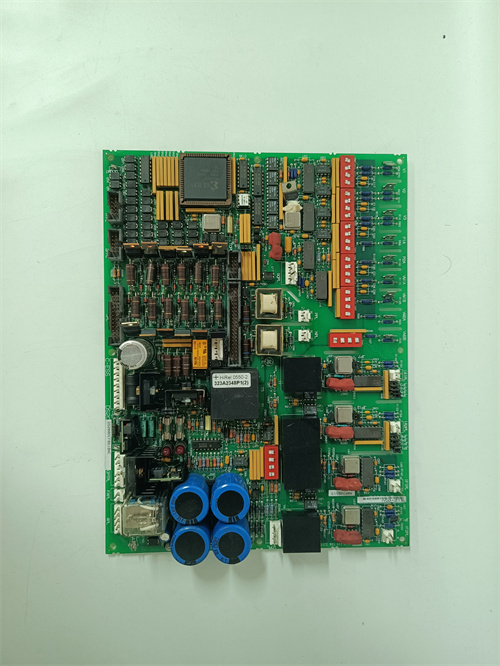
| Full Model | DS3800NPCR1A1A |
| Power Supply | +5V DC @ 5.2A, +15V DC @ 1.0A, -15V DC @ 0.8A |
| Temperature Inputs | 8 thermocouple + 8 RTD = 16 total channels (12-bit ADC, ±2°C / ±0.5°C) |
| Relay Outputs | 8 mechanical relays, 5A continuous @ 115VAC/30VDC (surge 10A) |
| SS Outputs | 4 solid-state relays, 3A continuous @ 24–48VDC |
| Tachometer Inputs | 2 channels (up to 10 kHz) |
| Communication | Mark V proprietary parallel backplane bus |
| Operating Temperature | 0°C to +60°C |
| LED Indicators | Power, Relay Run (8x amber), SS Run (4x green), Tach Fail (red x2), RTD Fault (yellow), Over-Temp Alarm, Backplane Active |
Advantages and Distinctive Features
-
Relay-Primary Hybrid + Tachometer Feedback: 8 high-current mechanical relays (5A) + 4 solid-state DC outputs (3A) + 2 tachometer inputs on a single board.
-
Dual Temperature Sensor Support (T/C + RTD): 8 thermocouple + 8 RTD inputs (16 total channels).
-
Higher Relay Current (5A): Supports larger AC/DC fans compared to 3A relay boards.
-
Higher Solid-State Current (3A): Supports larger DC auxiliary loads compared to 2A boards.
-
RTD Fault Detection: Continuous monitoring for open-circuit, short-circuit, or lead-wire degradation.
-
Baseline Revision A: The original version of this board—ideal for direct replacement in legacy systems.
-
Complete Galvanic Isolation: 2500V isolation on relay outputs.
-
Fan Speed Verification: Tachometer inputs allow CPU to confirm fan operation.
Typical Application Fields
-
Safety-Critical Mixed Fan Systems: Where high-power fan control, redundant temperature sensing, and fan failure detection are mandatory.
-
Mixed Fan Cabinets: Where high-power AC/DC fans and DC auxiliary devices coexist with both T/C and RTD sensors.
-
Nuclear Auxiliary Turbines: High reliability with redundant temperature sensing.
-
Legacy System Replacements: Direct drop-in replacement for original DS3800NPCR boards.
-
Climate-Controlled Indoor Installations: 0°C to +60°C range.
Comparison with Related Models
| Feature | DS3800NPCR1A1A | DS3800NPCR (Base) | DS3800NPCM1B1B | DS3800NMEC1E1E |
|---|---|---|---|---|
| Relay Outputs | 8 × 5A | 8 × 5A | 4 × 5A | 8 × 5A |
| SS Outputs | 4 × 3A | 4 × 3A | 8 × 3A | 4 × 2A |
| T/C + RTD Inputs | 8 + 8 = 16 | 8 + 8 = 16 | 8 + 8 = 16 | 4 + 8 = 12 |
| Tach Inputs | 2 channels | 2 channels | 2 channels | None |
| ADC Resolution | 12-bit (±2°C / ±0.5°C) | 12-bit (±2°C / ±0.5°C) | 16-bit (±1°C / ±0.5°C) | 24-bit (±0.5°C / ±0.3°C) |
| Predictive Maintenance | No | No | No | Yes |
| Operating Temp | 0°C to +60°C | 0°C to +60°C | -20°C to +65°C | -40°C to +85°C |
| Firmware | A | Unknown | B | E |
| Cost | High | High | High | Ultra-Premium |
Selection Recommendations
-
Choose the DS3800NPCR1A1A if:
-
You need 8 high-current mechanical relay outputs (5A) for main fans.
-
You also need 4 solid-state outputs (3A) for DC auxiliary devices.
-
You require both thermocouple and RTD inputs (16 total channels).
-
You require RTD fault detection for sensor integrity monitoring.
-
You require tachometer feedback for fan speed verification.
-
You have a climate-controlled environment (0°C to +60°C).
-
You need a direct replacement for an existing DS3800NPCR board.
-
-
Choose the DS3800NPCM1B1B if: You need 8 SS outputs and 4 relay outputs with improved accuracy and extended temperature range (-20°C to +65°C).
-
Choose the DS3800NMEC1E1E if: You need 8 relay outputs and 4 SS outputs without tachometer feedback but with predictive thermal modeling and extreme temperature range (-40°C to +85°C).
Critical Precautions
-
ESD Protection: Always wear a grounded wrist strap.
-
High-Voltage/Current Hazard (Relay): Relay outputs switch 115VAC/5A—lethal. Use proper insulation.
-
Relay Inductive Derating: For inductive fan motors, derate from 5A to 3.5A or use RC snubbers.
-
DC Polarity (SS): Solid-state outputs are DC-only and polarity-sensitive—reverse polarity destroys the MOSFET.
-
SS Voltage Limit: Do not exceed 48VDC—AC voltages cause catastrophic failure.
-
RTD Wiring: Use 3-wire Pt100 RTDs. All three wires must be connected. Open/short circuits trigger RTD Fault LED.
-
RTD Lead Resistance: Use wire with resistance ≤10Ω per lead for accurate measurements.
-
Tachometer Wiring: Use shielded twisted-pair cable. Connect shield to designated terminal—not at the fan end.
-
No Hot-Swap: Always depower the rack before insertion/removal.
-
Slot Assignment: Install in slots 8–10 (auxiliary I/O).
-
CPU Dependency: If backplane communication is lost, the board defaults to 100% fan speed—tachometer monitoring and RTD fault detection disabled in fallback mode.
-
Firmware Compatibility: The DS3800NPCR1A1A is compatible with Mark V CPU firmware v4.0 and above for full RTD support. For v3.x, RTD inputs may be partially disabled—confirm compatibility before purchasing.
SICK IM30-15NPS-ZW1
GE IC200CHS022G
ABB 3HAC16831-1 10.8V
.jpg)
Reviews
There are no reviews yet.