
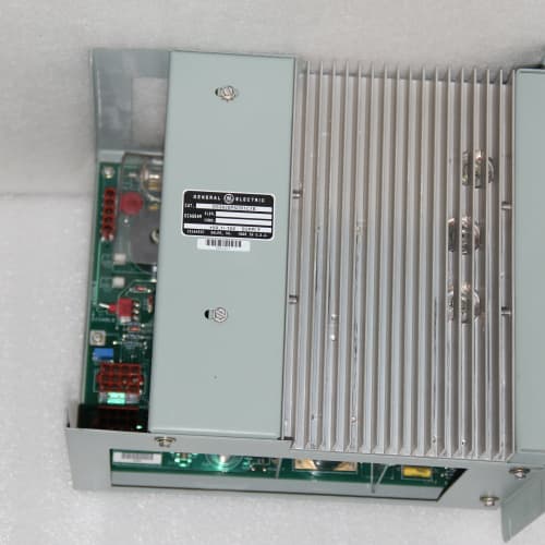
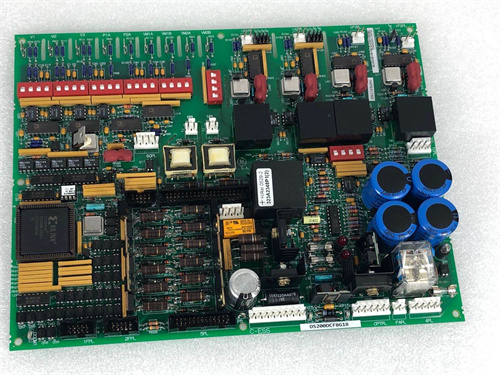
Description
Key Technical Parameters
| Parameter | Specification |
|---|---|
| Manufacturer | General Electric (GE) |
| Series | Mark V (Speedtronic) |
| Full Model | DS3800NHVF1A1A |
| Power Supply | +5V DC @ 3.8A, +15V DC @ 0.6A, -15V DC @ 0.4A |
| Temperature Inputs | 8 differential thermocouple channels (12-bit ADC, ±2°C accuracy) |
| Relay Outputs | 8 mechanical relays, 1A continuous @ 250VDC (surge 2A) |
| SS Outputs | 4 solid-state relays, 2A continuous @ 24–48VDC |
| Tachometer Inputs | 2 channels (up to 10 kHz) |
| Communication | Mark V proprietary parallel backplane bus |
| Operating Temperature | 0°C to +60°C |
| LED Indicators | Power, Relay Run (8x amber), SS Run (4x green), Tach Fail (red x2), Over-Temp Alarm, Backplane Active |
Advantages and Distinctive Features
-
Hybrid Output + Tachometer Feedback: The DS3800NHVF1A1A uniquely combines 8 high-voltage DC relay outputs, 4 low-voltage solid-state outputs, AND 2 tachometer inputs on a single board.
-
250VDC Relay Capability: Supports high-voltage exhaust fans.
-
Solid-State Auxiliary Outputs: Silent, maintenance-free switching for low-voltage circulating fans or alarms.
-
Fan Speed Verification: Tachometer inputs allow the CPU to confirm fan operation—critical for safety-critical systems.
-
Baseline Revision A: Ideal for direct replacement in legacy systems.
Typical Application Fields
-
Safety-Critical High-Voltage Cooling Systems: Where fan failure must be detected immediately.
-
High-Voltage Industrial Fan Systems: 220–250VDC exhaust fans with low-voltage auxiliary controls and speed monitoring.
-
Railway and Traction Applications: High-voltage DC cooling with 24VDC control circuits.
-
Legacy System Replacements: Direct drop-in replacement for original DS3800NHVF boards.
Comparison with Related Models
| Feature | DS3800NHVF1A1A | DS3800NHVF (Base) | DS3800NHVE1A1A | DS3800NHVD |
|---|---|---|---|---|
| Relay Outputs | 8 × 1A @ 250VDC | 8 × 1A @ 250VDC | 8 × 1A @ 250VDC | 8 × 1A @ 250VDC |
| SS Outputs | 4 × 2A @ 48VDC | 4 × 2A @ 48VDC | 4 × 2A @ 48VDC | None |
| Tach Inputs | 2 channels | 2 channels | None | None |
| T/C Inputs | 8 | 8 | 8 | 8 |
| ADC | 12-bit (±2°C) | 12-bit (±2°C) | 12-bit (±2°C) | 12-bit (±2°C) |
| Operating Temp | 0°C to +60°C | 0°C to +60°C | 0°C to +60°C | 0°C to +60°C |
| Firmware | A | Unknown | A | A/B |
| Cost | Medium-High | Medium-High | Medium | Medium |
Selection Recommendations
-
Choose the DS3800NHVF1A1A if:
-
You need 250VDC relay outputs for high-voltage exhaust fans.
-
You also need low-voltage solid-state outputs (24–48VDC) for auxiliary fans or alarms.
-
You require tachometer feedback for fan speed verification.
-
You have a climate-controlled environment (0°C to +60°C).
-
You need a direct replacement for an existing DS3800NHVF board.
-
-
Choose the DS3800NHVE1A1A if: You need the same hybrid outputs but do not require tachometer feedback.
-
Choose the DS3800NHVD if: You need only 250VDC relay outputs without solid-state auxiliary outputs.
Critical Precautions
-
ESD Protection: Always wear a grounded wrist strap.
-
Extreme High-Voltage Hazard: Relay outputs switch 250VDC—lethal voltage present on terminals. Observe all high-voltage safety procedures. Use wiring rated for ≥250VDC.
-
DC Polarity (Relay): Relay outputs are DC only—observe correct polarity.
-
DC Polarity (SS): Solid-state outputs are DC-only and polarity-sensitive—reverse polarity destroys the MOSFET.
-
Tachometer Wiring: Use shielded twisted-pair cable. Connect shield to designated terminal—not at the fan end.
-
Relay Current Limitation: Rated at 1A continuous @ 250VDC. Verify fan current does not exceed this limit.
-
SS Current Limitation: Rated at 2A continuous @ 24–48VDC.
-
Inductive Load Derating (Relay): Derate to 0.75A or use external RC snubbers (rated for 250VDC).
-
No AC Connection: Do not connect AC loads to either output type.
-
No Hot-Swap: Always depower the rack before insertion/removal.
-
Slot Assignment: Install in slots 8–10 (auxiliary I/O).
-
CPU Dependency: If backplane communication is lost, the board defaults to 100% fan speed—tachometer monitoring disabled in fallback mode.
-
Firmware Compatibility: The DS3800NHVF1A1A is compatible with all Mark V CPU firmware versions (v3.x and above). No specific CPU upgrade is needed.
A-B 25-RF027-CL
P+F KCD2-SOT-EX2
OMRON CP1E-E20SDR-A


Reviews
There are no reviews yet.