
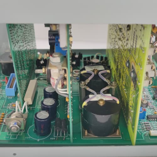
Description
Key Technical Parameters
| Parameter | Specification |
|---|---|
| Manufacturer | General Electric (GE) |
| Series | Mark V (Speedtronic) |
| Full Model | DS3800NGRA1F1F |
| Power Supply | +5V DC @ 5.0A, +15V DC @ 1.0A, -15V DC @ 0.7A (via backplane) |
| Temperature Inputs | 8 thermocouple (Type J/K/T, 24-bit ADC, ±0.5°C) + 8 RTD (Pt100, 3-wire, 24-bit ADC, ±0.3°C) = 16 total channels |
| Fan Outputs | 8 mechanical relays, 8A continuous @ 250VAC or 30VDC (surge 15A for 200ms) |
| Tachometer Inputs | 2 channels with predictive validation and adaptive filtering (up to 20 kHz) |
| Communication | Mark V proprietary parallel backplane bus |
| Operating Temperature | -40°C to +75°C (military-grade) |
| Storage Temperature | -55°C to +100°C |
| Vibration Resistance | 5g RMS, 10–500 Hz (MIL-STD-810G compliant) |
| LED Indicators | Power (green), Fan Run (8x amber), Tach Fail (red x2), Over-Temp Alarm (red), RTD Fault (yellow), Relay Degradation Warning (orange), Predictive Model Active (blue), Adaptive Filter Active (purple), Model Learning (flashing blue), Backplane Active (green), Bus Fault (red) |
Advantages and Distinctive Features
-
Dual Temperature Sensor Support (T/C + RTD): The DS3800NGRA1F1F is the only Mark V fan board with both thermocouple and RTD inputs. This allows mixed sensor types in the same cabinet or redundant monitoring (e.g., T/C for fast response, RTD for high accuracy).
-
16 Total Temperature Channels: 8 thermocouple + 8 RTD inputs provide unparalleled thermal monitoring density, eliminating the need for separate temperature input boards in most cabinets.
-
8A Mechanical Relays with Predictive Maintenance: Delivers 8A continuous output (15A surge) with real-time contact resistance monitoring and yellow “Relay Degradation” warning LED.
-
Dual Tachometer Inputs with Predictive Validation: Monitors fan speed and uses the predictive thermal model to validate performance, generating pre-failure warnings.
-
Predictive Thermal Modeling (Revision F): Learns cabinet thermal response during the first 24 hours, anticipating temperature changes and reducing overshoot by up to 50%.
-
24-Bit Ultra-High Precision ADC: ±0.5°C for thermocouples, ±0.3°C for RTDs—the highest accuracy in any Mark V fan board.
-
RTD Fault Detection: The DS3800NGRA1F1F continuously monitors RTD lead resistance and can detect open-circuit, short-circuit, or lead-wire degradation, illuminating a yellow “RTD Fault” LED.
-
Silver-Alloy Relay Contacts: Silver-cadmium-oxide contacts resist welding and pitting under high-inrush conditions.
-
500-Event Fault Log: Stores all temperature alarms, tach failures, RTD faults, relay degradation events, predictive model events, and fallback activations.
Typical Application Fields
-
Large Turbine Control Cabinets: Where both thermocouple and RTD sensors are used, or where redundant temperature monitoring is required.
-
Offshore Oil & Gas Platforms: Extreme temperature and vibration tolerance with mixed sensor support.
-
Desert Power Plants: 75°C upper limit with comprehensive thermal monitoring.
-
Arctic Compressor Stations: -40°C low-temperature tolerance.
-
Nuclear Auxiliary Turbines: High reliability with predictive diagnostics and redundant temperature sensing.
-
Research & Test Facilities: Where precise temperature monitoring with both sensor types is needed.
-
Safety-Critical Cooling Systems: With redundant temperature monitoring and fan speed verification.
Comparison with Related Models
| Feature | DS3800NGRA1F1F | DS3800NGRA1F1B | DS3800NFLA1D1D | DS3800NFMC1F1E |
|---|---|---|---|---|
| Output Type | Mechanical relay | Mechanical relay | Mechanical relay | Solid-state (DC only) |
| Output Current | 8A | 8A | 8A | 3A |
| Thermocouple Inputs | 8 channels | 8 channels | 8 channels | 8 channels |
| RTD Inputs | 8 channels | None | None | None |
| Total Temp Channels | 16 | 8 | 8 | 8 |
| Tachometer Inputs | 2 channels | 2 channels | 2 channels | 2 channels |
| ADC Resolution | 24-bit (±0.5°C / ±0.3°C) | 24-bit (±0.5°C) | 24-bit (±0.5°C) | 24-bit (±0.5°C) |
| Predictive Thermal Modeling | Yes | Yes | No | Yes |
| Predictive Tach Validation | Yes | Yes | No | Yes |
| Predictive Maintenance | Yes | Yes | Yes | No |
| RTD Fault Detection | Yes | No | No | No |
| Fault Log Capacity | 500 events | 500 events | 200 events | 500 events |
| Operating Temp | -40°C to +75°C | -40°C to +75°C | -40°C to +75°C | -40°C to +75°C |
| AC Fan Capability | Yes | Yes | Yes | No |
| Cost (Used) | Ultra-Premium+ | Ultra-Premium | Ultra-Premium | Ultra-Premium |
Selection Recommendations
-
Choose the DS3800NGRA1F1F if:
-
Your fans require mechanical relay outputs with 8A continuous rating (AC or DC).
-
Your cabinet uses both thermocouple and RTD temperature sensors, or you require redundant temperature monitoring.
-
You need tachometer feedback for speed verification and predictive validation.
-
You want predictive thermal modeling to proactively manage temperature.
-
Predictive relay maintenance is required to avoid unplanned downtime.
-
You require RTD fault detection for sensor integrity monitoring.
-
Your installation is in extreme environments (-40°C to +75°C) with high vibration.
-
You want the highest possible temperature monitoring density (16 channels).
-
-
Choose the DS3800NGRA1F1B if: You need 8A relays, tachometer feedback, and predictive modeling but only require thermocouple inputs (no RTDs).
-
Choose the DS3800NFLA1D1D if: You need 8A relays with tachometer feedback and predictive maintenance but without predictive thermal modeling.
-
Choose the DS3800NFMC1F1E if: You prefer solid-state DC outputs (3A) with tachometer feedback, predictive modeling, and predictive validation but cannot drive AC fans.
Critical Precautions
-
ESD Protection: The DS3800NGRA1F1F contains sensitive 24-bit ADC components. Always wear a grounded ESD wrist strap. Static damage to the ADC will degrade temperature accuracy.
-
RTD Wiring: Use 3-wire Pt100 RTDs with proper lead-wire compensation. The DS3800NGRA1F1F requires all three wires to be connected for accurate measurement. Open or shorted RTD inputs will trigger the yellow “RTD Fault” LED.
-
RTD Lead Resistance: For accurate measurements, use RTD extension wire with resistance ≤10Ω per lead. Higher resistance will reduce accuracy and may trigger lead-wire degradation warnings.
-
Relay Inductive Load Derating: The 8A rating applies to resistive loads. For inductive fan motors, derate to 6A or use an external RC snubber across each relay output.
-
Relay Contact Welding: Under severe short-circuit conditions (e.g., locked rotor), contacts may weld. The predictive maintenance circuit will detect increased contact resistance.
-
Tachometer Wiring: Use shielded twisted-pair cable. The adaptive filtering on the DS3800NGRA1F1F reduces noise sensitivity, but proper grounding is essential.
-
Predictive Model Learning Period: Requires a 24-hour learning period after first power-up (flashing blue LED). Do not interrupt power—interruption will reset the learning process.
-
Model Reset: If cabinet configuration changes, reset the predictive model via Mark V software to force a new learning cycle.
-
No Hot-Swap: Always depower the Mark V rack before inserting or removing the DS3800NGRA1F1F.
-
Slot Assignment: Install in auxiliary I/O slots (typically slots 8–10). Do not install in CPU or analog input slots—relay switching transients can couple noise into sensitive circuits.
-
CPU Dependency: The DS3800NGRA1F1F has no onboard logic. The Mark V CPU must process all temperature data, tachometer feedback, and send fan commands. If backplane communication is lost, the board defaults to 100% fan speed—all advanced features will be disabled in fallback mode.
-
Firmware Compatibility: Revision F firmware requires Mark V CPU firmware v5.5 or higher for full predictive modeling, predictive tach validation, RTD support, predictive maintenance, and 24-bit ADC functionality. If your CPU runs v5.0–v5.4, predictive modeling and tach validation will be disabled (basic tachometer reading, RTD reading, and predictive maintenance still function). For v4.x systems, the board reverts to 16-bit mode with no advanced features. Confirm compatibility before purchasing.
-
Power Supply Capacity: The DS3800NGRA1F1F draws 5.0A on the +5V rail—the highest of any Mark V board. Verify that your Mark V rack’s power supply has sufficient capacity. Overloading the +5V rail can cause system instability, corrupt the predictive model memory, and affect RTD measurement accuracy.
COFI TRE820 P/4
P+F KCD2-UT2-EX1
A-B 1756-PSCA2A

Reviews
There are no reviews yet.