
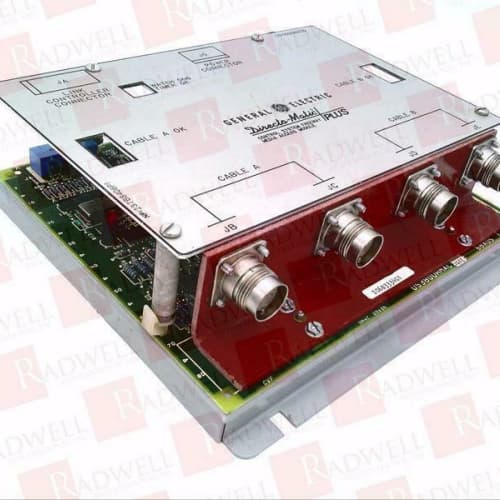
Description
Technical Specifications
-
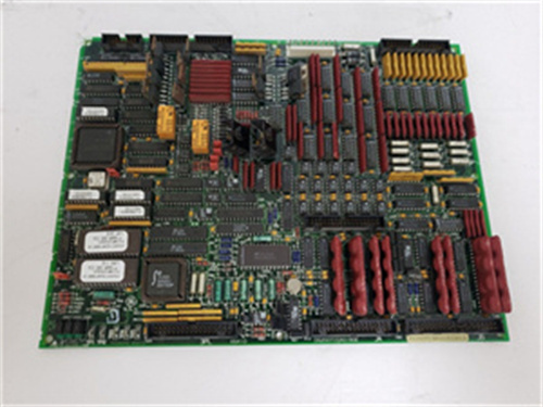
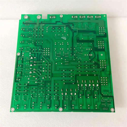
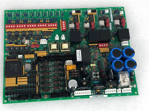
Product Type: Digital Relay & Remote Alarm Board (Revision 1C1B)
-
Part Number: DS3800DRRA1C1B
-
Manufacturer: General Electric (GE)
-
System Compatibility: GE Speedtronic Mark IV Turbine Control Systems (Rev. M and later)
-
Output Channels: 16 digital outputs (Form C – SPDT relays)
-
Contact Rating: 5A @ 250VAC or 5A @ 30VDC (resistive); 3A @ 250VAC (inductive)
-
Surge Suppression: Enhanced RC snubbers + bidirectional TVS diodes (upgraded from standard flyback)
-
Indicators: Front-panel LEDs per channel (no mechanical flags)
-
Isolation: 2500Vrms reinforced opto-isolation with improved common-mode transient immunity (> 50kV/µs)
-
Coil Power Regulation: Upgraded switching regulator for relay coils (reduces heat vs. linear regulators)
-
Temperature Range: -40°C to +70°C
-
Terminal Connections: 34-pin edge connector + dedicated screw terminal block
-
MTBF: > 200,000 hours (MIL-HDBK-217F)
Key Features & Advantages
-
Upgraded Coil Power Regulation: The GE DS3800DRRA1C1B uses a switching regulator for relay coil excitation, reducing heat dissipation by ~25% compared to the linear regulators on earlier revisions. This extends the life of adjacent boards and reduces cooling requirements.
-
Enhanced Transient Immunity: Improved common-mode transient immunity (> 50kV/µs) ensures reliable operation in electrically noisy environments with large VFDs or arc furnaces.
-
Higher Inductive Load Rating: Rated 3A inductive (vs. 2A on many earlier boards), suitable for driving medium-sized contactors and solenoids in remote junction boxes.
-
Reinforced Isolation: 2500Vrms with reinforced insulation ensures reliable communication with remote equipment despite ground potential differences.
-
TVS Diode Protection: Bidirectional TVS diodes (upgraded from standard flyback diodes) provide faster clamping and better protection against high-energy transients from inductive loads.
-
Screw Terminal Block: Simplifies field wiring and maintenance.
-
Fast Response: < 10ms switching time for alarm annunciation and critical signaling.
Typical Application Cases
-
Plant DCS Interfacing: The GE DS3800DRRA1C1B sends turbine status signals (overspeed, high temperature, low pressure) to plant DCS systems (e.g., Emerson Ovation, ABB 800xA) via dry relay contacts.
-
Remote Alarm Panels: Drives annunciator panels in the central control room, alerting operators to turbine events.
-
Emergency Shutdown Signaling: Transmits trip signals to plant-wide ESD systems for coordinated safety interlocks.
-
Data Logging Triggers: Provides contact closures to event recorders and data loggers for post-trip analysis.
-
Mimic Panel Display: Drives large mimic panels showing turbine operating status in older control rooms.
Competitive Comparison
| Feature | GE DS3800DRRA1C1B | GE DS3800DRRA (Base) | Modern DCS Output Module |
|---|---|---|---|
| Coil Regulation | Switching (efficient) | Linear (hotter) | N/A (solid-state) |
| Inductive Load Rating | 3A @ 250VAC | 2A @ 250VAC | 0.5A @ 24VDC |
| Transient Immunity | > 50kV/µs | 30kV/µs (typical) | 10kV/µs (typical) |
| Surge Suppression | RC + TVS (bidirectional) | RC + flyback | External required |
| Isolation | 2500Vrms reinforced | 2500Vrms | 500Vrms |
| Visual Indication | LEDs only | LEDs only | LEDs + software status |
| Temperature Range | -40°C to +70°C | -40°C to +70°C | 0°C to +60°C |
| Compatibility | Dedicated Mark IV | Dedicated Mark IV | Universal fieldbus |
The GE DS3800DRRA1C1B offers improved efficiency and transient protection over the base version, making it the preferred revision for electrically harsh environments. Modern DCS modules provide digital communication and diagnostics but require protocol conversion and cannot directly interface with the Mark IV backplane.
Selection Guidelines & Precautions
-
Cable Length and Voltage Drop: For remote wiring > 500m, verify voltage drop stays within device pull-in limits. Keep cable resistance < 10Ω per contact for 24VDC circuits.
-
Ground Potential Differences: While the GE DS3800DRRA1C1B provides 2500Vrms isolation, if ground potential differences are extreme (e.g., > 1000V), install additional isolation relays at the remote end.
-
No Mechanical Flags: Use external latching relays for applications requiring visual alarm history retention after power loss.
-
Terminal Block Wiring: Use ferrules on stranded wires to prevent loose connections and intermittent signals.
-
Inductive Load Derating: For loads exceeding 3A inductive, use the GE DS3800DRRA1C1B to drive an external interposing relay to protect contacts.
-
Shielded Cabling: Use shielded twisted-pair cable for all remote wiring; ground the shield at one end (typically DCS side) to prevent ground loops.
-
Backplane Compatibility: The GE DS3800DRRA1C1B requires Mark IV backplane Rev. M or later. Verify pin compatibility; older racks may need adapter boards.
-
ESD Handling: Use ESD-safe practices; opto-isolators are sensitive to static discharge.
-
Sourcing: The GE DS3800DRRA1C1B is obsolete; only available through aftermarket suppliers. Request:
-
Functional test report (all 16 channels tested under rated load)
-
Contact resistance < 0.1Ω (new) or < 0.5Ω (refurbished)
-
Surge suppression verification (RC + TVS functionality)
-
Visual inspection for burnt contacts or overheated joints
-
Electrolytic capacitor replacement (if aged > 10 years)
-
-
Spare Strategy: Keep one spare GE DS3800DRRA1C1B on-site. For critical circuits (fire detection, overspeed), consider redundant configuration with two boards in series for fail-safe operation.
A-B 1756-OB32
A-B 1756-OB32
A-B 1794-ACN15


Reviews
There are no reviews yet.