
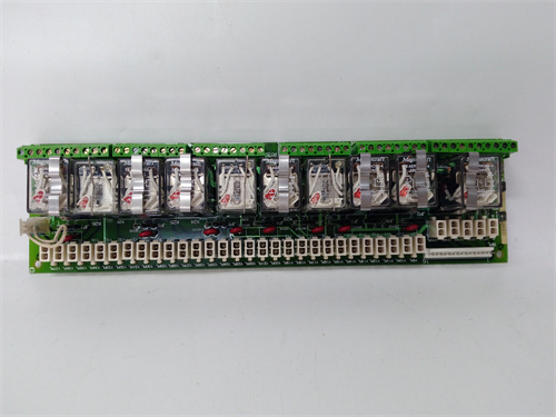
Description
Key Technical Parameters
| Parameter | Specification |
|---|---|
| Brand | GE / Emerson |
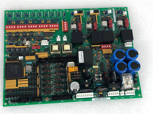
| Model | DS215TCQFG1AZZ01A |
| Thermocouple Inputs | 8 channels, configurable for Type J, K, T, E, R, S, B, N |
| RTD Inputs | 4 channels (selectable via configuration, 3‑wire or 4‑wire PT100) |
| Quadrature/Encoder Inputs | 2 channels (A/B/Z), 0.1 Hz – 150 kHz, differential or single‑ended |
| Quadrature Decoding | x1, x2, x4 modes |
| Position Resolution | Up to 0.025° (with 14‑bit absolute encoder) |
| Analog Outputs | 4 channels, 4–20 mA or 0–10 V (configurable) |
| Fiber‑Optic Communication Ports | 2 x (full‑duplex, 100 Mbps, ST or SC connectors, configurable) |
| Fiber‑Optic Transmission Distance | Up to 2 km (multimode), up to 10 km (singlemode) |
| Communication Protocols | GE SRTP (fiber), proprietary GE fiber‑optic link protocol |
| Isolation | Channel‑to‑channel and channel‑to‑ground (1500 VAC) |
| Cold Junction Compensation | Built‑in with automatic compensation and redundant reference sensors |
| Accuracy | ±0.04% of full scale (thermocouple), ±0.02% of full scale (RTD) |
| Resolution | 20‑bit (thermocouple/RTD inputs), 16‑bit (analog outputs) |
| Diagnostics | Thermocouple burnout detection, RTD open/short detection, quadrature phase‑error detection, fiber‑optic link health monitoring, self‑test routines |
| Protection | Overvoltage, reverse polarity, transient suppression, power fail detection |
| Communication | Fiber‑optic (Mark V backplane communication) and additional fiber‑optic output for remote data transmission |
| Cooling | Passive – no fan |
| Dimensions | 260 × 180 × 35 mm (standard Mark V Eurocard) |
| Operating Temp | –20°C to +65°C |
| Certifications | CE, UL, CSA, ATEX (Class I, Div 2), IEC 61508 SIL‑1 |
Advantages & Features
-
Integrated Fiber‑Optic Communication – The DS215TCQFG1AZZ01A includes two fiber‑optic communication ports for direct, noise‑immune data transmission over distances up to 10 km, eliminating the need for separate fiber‑optic communication modules.
-
Triple‑Function Integration – Combines temperature measurement, quadrature encoder inputs, and fiber‑optic communication in a single module, reducing cabinet space, module count, and system complexity.
-
High‑Accuracy Temperature Measurement – 20‑bit resolution with ±0.04% thermocouple and ±0.02% RTD accuracy ensures precise temperature measurement.
-
Precise Speed/Position Feedback – 2 quadrature encoder channels with x1/x2/x4 decoding, 150 kHz maximum frequency, and 0.025° position resolution.
-
Extended Distance Communication – Supports transmission up to 10 km (singlemode) or 2 km (multimode), enabling remote monitoring and control of distributed turbine assets.
-
Quadrature Phase‑Error Detection – Monitors the phase relationship between quadrature signals (A/B) and detects phase errors indicating sensor misalignment, wiring faults, or encoder damage.
-
EMI Immunity – Fiber‑optic communication provides complete immunity to electromagnetic interference, critical in high‑voltage switchyards and turbine environments.
-
Redundant Fiber‑Optic Paths – Two fiber‑optic ports support redundant communication paths for high‑availability applications.
-
Integrated Analog Outputs – 4 analog outputs for transmitting temperature or speed/position data to local monitoring systems.
-
Built‑in Cold Junction Compensation – Automatic cold junction compensation with redundant reference sensors for thermocouple inputs.
-
Extended Operating Temperature – Rated for –20°C to +65°C, suitable for harsh environmental conditions.
-
Hot‑Swap Capable – Supports live insertion/removal with safety interlocks, minimizing downtime.
-
High Reliability – Military‑grade components, conformal‑coated PCB, and robust design with MTBF of 88,000 hours.
Application Cases
-
Remote Gas Turbine Monitoring – Measures turbine rotor speed and exhaust gas temperature with data transmitted via fiber‑optic link to a remote control room up to 10 km away.
-
Distributed Compressor Stations – Monitors compressor shaft speed and bearing temperatures with fiber‑optic communication to a central SCADA system over long distances.
-
High‑EMI Environments – Provides temperature and speed data from electrically noisy environments (e.g., high‑voltage switchyards) with fiber‑optic noise immunity.
-
Offshore Platforms – Transmits data from turbine sensors on offshore platforms to onshore control centers via long‑haul fiber‑optic links.
-
Redundant Control Systems – Two fiber‑optic ports provide redundant communication paths for critical turbine control applications.
-
Retrofit Space Optimization – Replaces separate temperature, encoder, and fiber‑optic communication modules with a single integrated module.
Comparison with Competitor Products
| Feature | GE DS215TCQFG1AZZ01A | GE DS215TCQAG1 + Fiber Module | Siemens S7‑1500 (AI + Encoder + Fiber) | ABB AC800M (AI + Encoder + Fiber) |
|---|---|---|---|---|
| Thermocouple Inputs | 8 | 8 | 8 | 8 |
| RTD Inputs | 4 | 4 | 4 | 4 |
| Quadrature Inputs | 2 (x4) | 2 (x4) | 2 | 2 |
| Max Frequency | 150 kHz | 150 kHz | 100 kHz | 100 kHz |
| Position Resolution | 0.025° | 0.025° | 0.036° | 0.036° |
| Analog Outputs | 4 | 4 | 4 | 4 |
| Fiber‑Optic Ports | 2 (built‑in) | Requires separate module | Requires separate module | Requires separate module |
| Max Distance | 10 km | Depends on separate module | Up to 2 km | Up to 2 km |
| EMI Immunity | Yes (fiber) | Yes (fiber) | Yes (fiber) | Yes (fiber) |
| Hot‑Swap | Yes | Yes | No | No |
| Cabinet Footprint | 1 slot | 2+ slots | 3+ slots | 3+ slots |
| MTBF | 88,000 hrs | Combined (~85,000 hrs) | ~80,000 hrs | ~76,000 hrs |
Key Differentiator: The DS215TCQFG1AZZ01A uniquely combines temperature measurement, quadrature encoder inputs, and fiber‑optic communication in a single module, with dual fiber‑optic ports supporting distances up to 10 km, providing the most integrated solution for distributed, noise‑immune monitoring and control.
Selection Suggestions
-
Evaluate Communication Distance – The DS215TCQFG1AZZ01A supports up to 10 km (singlemode) or 2 km (multimode), ideal for remote monitoring and distributed assets.
-
Assess EMI Environment – Use fiber‑optic communication for high‑EMI environments such as high‑voltage switchyards, turbine decks, and industrial facilities.
-
Identify Temperature and Encoder Requirements – Provides 8 thermocouple, 4 RTD, and 2 quadrature inputs; for larger needs, supplement with additional modules.
-
Consider Redundancy – Two fiber‑optic ports support redundant communication paths for critical applications.
-
Determine Fiber‑Optic Type – Select multimode (2 km) or singlemode (10 km) connectors based on distance requirements.
-
Firmware – The “AZZ01A” suffix indicates a specific firmware version; verify compatibility with your Mark V system.
-
Spares – Lead time typically 8–10 weeks; maintain a spare module for critical installations.
Precautions
-
ESD Protection – Use wrist strap and anti‑static handling during installation, especially for sensitive encoder, thermocouple, and fiber‑optic transceiver components.
-
Fiber‑Optic Handling – Do not bend fiber cables below 50 mm radius; keep dust caps on when not connected. Clean fiber connectors with appropriate cleaning tools before connection.
-
Thermocouple Wiring – Use thermocouple‑grade extension wire of the same type; avoid copper wire between sensor and module.
-
RTD Wiring – For 3‑wire RTDs, ensure the third wire is properly connected for lead compensation.
-
Encoder Wiring – Use shielded twisted‑pair cables for quadrature inputs; observe proper termination and grounding.
-
Cold Junction Compensation – Ensure cold junction sensors are protected from drafts and heat sources.
-
Grounding – Connect earth lug directly to system ground with 6 mm² wire; avoid ground loops, especially with thermocouple and encoder inputs.
-
Commissioning – Verify thermocouple/RTD readings with known sources; verify encoder quadrature signals for correct phase, amplitude, and decoding mode; test fiber‑optic communication with loopback or remote receiver.
-
Firmware Updates – Use only GE’s official tool for firmware updates.
-
Periodic Inspection – Check for dust accumulation on heatsink, fiber‑optic connectors, and connector integrity annually; clean fiber connectors as needed.
Summary
The DS215TCQFG1AZZ01A is a unique, triple‑function module for GE Speedtronic Mark V turbine control systems, combining high‑accuracy temperature measurement, integrated quadrature encoder inputs, and integrated fiber‑optic communication in a single module for noise‑immune data transmission over extended distances. Its key strengths include 8 thermocouple inputs (Types J, K, T, E, R, S, B, N), 4 RTD inputs, 2 quadrature encoder inputs with x1/x2/x4 decoding, 150 kHz maximum frequency, 0.025° position resolution, 4 analog outputs, 20‑bit resolution, ±0.04% thermocouple and ±0.02% RTD accuracy, 2 fiber‑optic communication ports with distances up to 10 km, GE SRTP and proprietary fiber‑optic protocols, redundant cold junction compensation, quadrature phase‑error detection, extended –20°C to +65°C operating range, fiber‑optic backplane, hot‑swap capability, and passive cooling. Ideal for remote gas turbine monitoring, distributed compressor stations, high‑EMI environments, offshore platforms, redundant control systems, and retrofit space optimization, it provides the most integrated fiber‑optic triple‑function solution for Mark V systems. When paired with the Mark V controller and properly maintained, the DS215TCQFG1AZZ01A delivers reliable, noise‑immune, and long‑distance monitoring and control service for decades.
A-B 1770-KF2
A-B 1756-IF16
SCHNEIDER 140CRA93200
A-B 1756-OF8



Reviews
There are no reviews yet.