
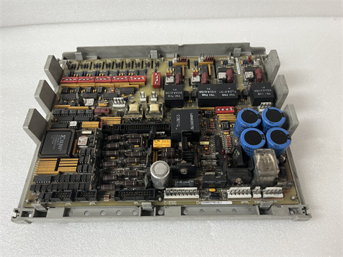
Description
Key Technical Parameters
| Parameter | Specification |
|---|---|
| Function | Remote terminal board for field I/O with integrated fieldbus (ultimate capacity, coated, advanced fieldbus & diagnostics) |
| Terminal Capacity | 96 terminals (6x 16-terminal blocks) – highest in Mark V family |
| Output Current Capacity | 3A per channel – highest in Mark V family |
| I/O Types Supported | Analog inputs (4-20mA, 0-10V), digital inputs (24-125 VDC), digital outputs (relay/transistor), thermocouple, RTD, and smart fieldbus devices |
| Wire Gauge | 12-22 AWG (solid/stranded) for conventional I/O; fieldbus uses dedicated shielded cable |
| Terminal Type | Screw-clamp (rise-clamp) with dual-wire entry capability for conventional I/O; fieldbus connectors (e.g., SUB-D or M12) |
| Fuse Protection | 24 onboard fuses – one per output channel, user-replaceable, 3A rating, with LED indication and current sensing |
| Diagnostic Indicators | 38 LEDs – 24 channel status LEDs (green/red), 6 block-level “CHANNEL BLOCK” LEDs, 1 “PWR OK” LED, 1 “COAT OK” LED (coating integrity), 1 “WARN” LED (pre-failure), 1 “BUS ACT” LED (fieldbus active), 1 “FB-ERR” LED (fieldbus error), 1 “FB-LINK” LED (fieldbus link), 1 “S-COM” LED (serial communication), 1 “COM ACT” LED (communication active), 1 “DIAG” LED (diagnostic system active) |
| Fieldbus Interface | Integrated fieldbus port (Profibus DP, MODBUS RTU, or Foundation Fieldbus – configurable) |
| Fieldbus Diagnostics | Real-time fieldbus communication status, device health monitoring, network statistics, bus error logging |
| Enhanced Monitoring | Individual channel current sensing (up to 3A), fuse health monitoring, temperature sensing, channel impedance monitoring, remote communication status, diagnostic self-test, channel health trending |
| Isolation | 2,500 VAC isolation between field side and control side; fieldbus interface galvanically isolated |
| Conformal Coating | Acrylic (Humiseal 1B73), 0.002-0.003″ thickness, 1,000 hr salt-spray rated |
| Temperature Range | 0 to +60°C ambient (extended from +55°C) |
| Form Factor | 1.5-slot width – requires adjacent empty slot |
| Weight | 0.82 kg (approx. 1.81 lbs) |
Advantages & Core Features
-
Absolute highest terminal capacity with conformal coating, fieldbus, and advanced diagnostics – The DS200RTBAG3AGC provides 96 terminals, 3A per channel output capacity, conformal coating, integrated fieldbus, and the most comprehensive diagnostic system in the Mark V family.
-
Absolute highest output current capacity (3A per channel) – Supports direct control of high-power field devices without external interposing relays.
-
Integrated fieldbus with reduced wiring – The fieldbus interface reduces individual field wiring runs by enabling a single digital bus to multiple smart devices.
-
Conformal coating with integrity monitoring – The white “COAT OK” LED provides real-time validation of coating integrity.
-
Comprehensive LED array – 38 LEDs provide granular status: 24 channel status LEDs, 6 block-level LEDs, “PWR OK”, “COAT OK”, “WARN” (pre-failure), “BUS ACT” (fieldbus active), “FB-ERR” (fieldbus error), “FB-LINK” (fieldbus link), “S-COM” (serial communication), “COM ACT” (communication active), and “DIAG” (diagnostic system active).
-
Pre-failure amber WARN LED – Alerts operators to potential issues before a full fault occurs, enabling predictive maintenance.
-
Channel impedance monitoring – Detects changes in field wiring impedance, indicating loose connections, cable degradation, or sensor faults.
-
Channel health trending – The monitoring system tracks channel performance over time, identifying gradual degradation before failure.
-
Diagnostic self-test – Performs a comprehensive self-test on power-up, verifying all channels, fuses, monitoring circuits, fieldbus interface, and communication interfaces.
-
Fieldbus error logging – Stores bus error events for diagnostic analysis.
-
Fieldbus protocol flexibility – Supports Profibus DP, MODBUS RTU, or Foundation Fieldbus (field-configurable via DIP switches).
-
Enhanced monitoring – Individual channel current sensing (up to 3A), impedance monitoring, temperature monitoring, fieldbus communication health, remote communication monitoring, and channel health trending.
-
Extended temperature range – 0 to +60°C ambient allows use in warm environments.
-
Individual channel fusing – Each conventional output channel is protected by a user-replaceable fuse (24 total) with LED indication.
-
Galvanic isolation – 2,500 VAC isolation protects the Mark V backplane; fieldbus interface is also galvanically isolated.
-
1.5-slot form factor – Accommodates the highest component density.
Key Differences vs. DS200RTBAG3AFB (Previous Ultimate Fieldbus Model)
| Feature | DS200RTBAG3AFB (Fieldbus) | DS200RTBAG3AGC (Advanced Fieldbus + Diag) |
|---|---|---|
| Diagnostic LEDs | 34 | 38 |
| DIAG LED | No | Yes |
| Impedance Monitoring | Yes | Yes |
| Channel Health Trending | No | Yes |
| Diagnostic Self-Test | No | Yes |
| Fieldbus Error Logging | No | Yes |
| Availability | Exceedingly rare++++ | Exceedingly rare+++++ |
| Cost | Premium+++++ | Premium++++++ |
Application Cases
-
Mega offshore platform with extreme I/O, harsh environment, fieldbus, and predictive maintenance – A North Sea mega-platform uses the DS200RTBAG3AGC to provide 96 terminals and 3A outputs for direct control of high-power actuators, Profibus DP communication to smart devices, and advanced diagnostics. The channel health trending detected a gradual increase in current draw on a critical circuit over 8 months, enabling preventive maintenance before a failure occurred. The DIAG LED confirms the diagnostic system is operational.
-
Coastal 1,000 MW combined-cycle with Foundation Fieldbus and advanced monitoring – A Florida mega-plant uses the DS200RTBAG3AGC for its 96-terminal capacity, 3A outputs, Foundation Fieldbus, and advanced diagnostics. The impedance monitoring detected a gradual increase in resistance on a critical control circuit, allowing preventive maintenance before a failure occurred.
-
Chemical plant with H₂S exposure and critical control circuits – A petrochemical facility uses the DS200RTBAG3AGC with MODBUS RTU to interface with gas detectors and temperature transmitters in H₂S-exposed areas, while providing 96 terminals and 3A outputs for conventional I/O. The diagnostic self-test provides confidence in the integrity of critical safety circuits.
-
Nuclear plant with rigorous predictive maintenance – A nuclear facility uses the DS200RTBAG3AGC for its advanced diagnostics (impedance monitoring, channel health trending, self-test, fieldbus error logging), enabling predictive maintenance of critical remote I/O circuits.
Comparison with Related Variants
| Feature | DS200RTBAG3AGC (Ultimate, Adv Fieldbus) | DS200RTBAG3AFB (Ultimate, Fieldbus) | DS200RTBAG3ABB (Ultimate, Coated) | DS200RTBAG2AGC (G2A, Fieldbus) |
|---|---|---|---|---|
| Terminal Capacity | 96 | 96 | 96 | 80 |
| Output Current Capacity | 3A | 3A | 3A | 2A |
| Conformal Coating | Yes | Yes | Yes | Yes |
| Fieldbus Interface | Yes | Yes | No | Yes |
| Diagnostic LEDs | 38 | 34 | 28 | 32 |
| Block-Level LEDs | Yes (6) | Yes (6) | No | Yes (5) |
| Impedance Monitoring | Yes | Yes | No | Yes |
| Diagnostic Self-Test | Yes | No | No | No |
| Channel Health Trending | Yes | No | No | No |
| Fieldbus Error Logging | Yes | No | No | No |
| DIAG LED | Yes | No | No | No |
| Temp Range | 0 to +60°C | 0 to +60°C | 0 to +60°C | 0 to +60°C |
| Slot Width | 1.5-slot | 1.5-slot | 1.5-slot | 1-slot |
| Availability | Exceedingly rare+++++ | Exceedingly rare++++ | Exceedingly rare+++ | Exceedingly rare+++ |
| Cost | Premium++++++ | Premium+++++ | Premium++++ | Premium++++ |
Selection Suggestions
-
Assess I/O density, current, environmental, fieldbus, and diagnostic requirements – Select the DS200RTBAG3AGC if you need more than 80 terminals, more than 2A per channel, conformal coating, fieldbus integration, AND the highest level of diagnostics (impedance monitoring, channel health trending, self-test, fieldbus error logging, block-level LEDs, DIAG LED). This is the only board that combines all at the ultimate capacity level.
-
Confirm fieldbus protocol – Verify that your field devices support Profibus DP, MODBUS RTU, or Foundation Fieldbus.
-
Evaluate diagnostic requirements – The DS200RTBAG3AGC is essential if you need diagnostic self-test, channel health trending, fieldbus error logging, or the DIAG LED for confirmation of diagnostic system status.
-
Assess environmental conditions – The board is essential if your installation is harsh (coastal, offshore, chemical, high-humidity, high-temperature).
-
Confirm slot availability – The board requires 1.5-slot clearance. Verify adjacent slot is empty.
-
Confirm signal types – Ensure the board supports the required field signal types.
-
Verify fuse ratings – Ensure that the 3A fuse ratings match your output channel current requirements.
-
Verify fieldbus cable routing – Use proper shielded fieldbus cables. Route fieldbus cables separately from power cables.
-
Procurement – The DS200RTBAG3AGC is the rarest Mark V remote terminal board. Only purchase from suppliers providing:
-
Coating thickness verification
-
Fieldbus communication testing (Profibus DP, MODBUS RTU, Foundation Fieldbus)
-
LED testing (all 38 LEDs)
-
Channel verification (all 96 terminals, 3A per channel)
-
Fuse verification (24 fuses, 3A)
-
Current sensing validation (3A per channel)
-
Impedance monitoring validation
-
Diagnostic self-test verification
-
Channel health trending verification
-
Fieldbus error logging validation
-
DIAG LED functionality verification
Lead times: 34-40 weeks.
-
-
Stock spares – Maintain at least two spares on-site.
Important Precautions
-
Power down completely – De-energize the entire system before insertion or removal. Hot-swapping is not supported.
-
Slot clearance – Ensure 1.5-slot clearance (adjacent slot empty).
-
ESD protection – Use wrist strap and anti-static mat.
-
Wiring termination – Ensure conventional field wires are properly stripped and securely clamped. Use appropriate wire gauge (12-22 AWG).
-
Fieldbus cabling – Use only shielded fieldbus cables. Ensure proper termination and grounding.
-
Protocol configuration – Set DIP switches correctly for the desired fieldbus protocol before installation.
-
Coating integrity check – On power-up, verify white “COAT OK” LED illuminates. If off, remove and return for recoating.
-
Pre-failure WARN LED – If amber WARN LED illuminates, investigate immediately.
-
DIAG LED – If the DIAG LED fails to illuminate on power-up, the diagnostic system has detected a fault. Remove and return for repair.
-
Fieldbus network management – Ensure proper network termination and addressing. Monitor FB-ERR LED for network errors.
-
Fuse replacement – Replace fuses only with specified types and ratings (3A).
-
Check total current draw – Ensure total current draw on each rail does not exceed capacity.
-
Signal segregation – Route conventional analog/digital signals separately from fieldbus cables.
-
Cleaning – Use only dry compressed air (max 50 PSI, 30 cm distance). No solvents, alcohol, or brushes.
-
Storage – Store at 10-30°C, 20-50% RH. Rotate every 3 years.
Final Expert Recommendation
The DS200RTBAG3AGC represents the absolute pinnacle of Mark V remote terminal board technology, combining the highest terminal capacity (96 terminals), highest output current capacity (3A per channel), conformal coating, extended temperature range, integrated fieldbus interface (Profibus DP, MODBUS RTU, or Foundation Fieldbus), and the most comprehensive diagnostic system ever offered on a Mark V board – including 38 LEDs, pre-failure warning, impedance monitoring, channel health trending, diagnostic self-test, fieldbus error logging, block-level status, remote communication monitoring, and dedicated diagnostic system status (DIAG LED). It is the definitive solution for the most extreme distributed control installations requiring maximum density, current, protection, fieldbus integration, and diagnostic visibility.
Select the DS200RTBAG3AGC only when:
-
You have more than 80 remote field connections to terminate (up to 96)
-
Your output devices require more than 2A per channel (up to 3A)
-
You need fieldbus integration (Profibus DP, MODBUS RTU, or Foundation Fieldbus)
-
Your installation is harsh (coastal, offshore, chemical, high-humidity, high-temperature)
-
You need the highest level of diagnostic visibility (38 LEDs, block-level status, pre-failure warning)
-
You require impedance monitoring, channel health trending, and diagnostic self-test for predictive maintenance
-
You need fieldbus error logging for network analysis
-
You have 1.5-slot clearance available
For most applications, the DS200RTBAG3AFB (ultimate capacity, coated, fieldbus, standard diagnostics) provides excellent protection, capacity, and fieldbus at significantly lower cost and lead time. The DS200RTBAG3AGC should be reserved for the most demanding applications where the combination of ultimate capacity, protection, fieldbus, and advanced diagnostics is absolutely essential.
When sourcing the DS200RTBAG3AGC, ensure comprehensive documentation – coating verification, fieldbus communication validation, LED testing, channel verification, current sensing validation, impedance monitoring validation, diagnostic self-test verification, channel health trending verification, and fieldbus error logging validation. Given its exceedingly rare availability, maintain at least two spares on-site. Properly deployed, this board provides years of reliable, ultra-high-density, high-current, protected remote I/O with fieldbus integration and unparalleled diagnostic visibility for Mark V turbine control systems in the most challenging operating environments.
GE IS200VVIBH1CAC
Rolls-Royce H1127.0101
TRICONEX 3625

.jpg)


Reviews
There are no reviews yet.