
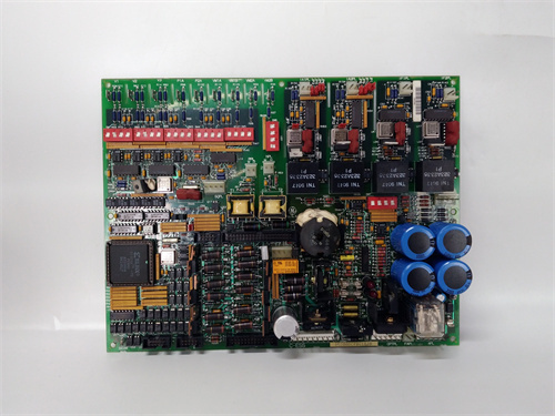
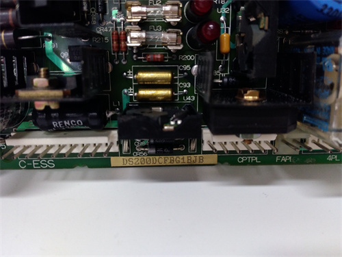
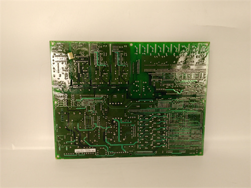
Description
Key Technical Parameters & Specifications
Type: Primary Power Supply Converter Board – 10A Continuous Output Version with Conformal Coating (acrylic-based, 0.003-inch thickness) and Bus Extension Interface (I²C-based diagnostic and current-sharing communication bus).
Compatibility: Exclusively designed for the GE Mark V Speedtronic series (firmware revisions R, S, and T). The DS200PCCAG10ACB is a direct replacement for the DS200PCCAG10A (non-coated version) and is backward-compatible with DS200PCCAG5, DS200PCCAG7, and DS200PCCAG10 boards, provided the backplane supports the additional bus extension pins. However, the conformal coating gives the DS200PCCAG10ACB a distinct advantage in high-humidity and corrosive environments where the uncoated DS200PCCAG10A would fail prematurely.
Input Voltage: Accepts a wide range of AC and DC inputs – 115 VAC ±10% at 47-63 Hz, or 125 VDC ±10% (nominal). The DS200PCCAG10ACB features automatic input detection and seamless transition between AC and DC sources, with prioritization favoring DC input to reduce harmonic distortion on the AC line. The bus extension interface allows remote monitoring of input voltage stability, with data sampled at 1 kHz and buffered for diagnostic retrieval.
Primary Outputs:
-
+5 VDC Logic Rail: 10A continuous, 12A peak (for 10-second transients) – the defining specification maintained across the ACB variant.
-
+15 VDC Analog Rail: 3A continuous, 4A peak.
-
-15 VDC Analog Rail: 2A continuous, 2.5A peak.
-
+24 VDC Field I/O Rail: 1.5A continuous (isolated).
Secondary Outputs (Auxiliary):
-
+3.3 VDC Standby: 0.5A continuous for wake-on-LAN and diagnostic keep-alive circuits – with conformal coating ensuring reliability in humid standby conditions.
-
Diagnostic Reference Voltage: +2.5 VDC precision reference (0.1% tolerance) available on the bus extension connector for external calibration and monitoring equipment.
Efficiency: Greater than 85% at full load (10A on +5V rail), with power factor correction (PFC) achieving 0.99 typical. The conformal coating does not affect thermal performance, as the coating is applied only to component bodies and not to the heatsink or fan surfaces.
Connectors:
-
J1: High-density 64-pin backplane connector for primary power delivery and status signaling.
-
J2: 6-pin programming header for firmware updates and configuration of current-sharing parameters.
-
J3: 10-pin bus extension connector (dedicated to the ACB variant) providing I²C diagnostic bus access, precision reference voltage, and auxiliary current-sharing synchronization signals.
-
TB1 and TB2: Two 4-pin auxiliary terminals for external fault monitoring and remote voltage sense lines.
Protection Features:
-
Overvoltage protection (OVP) on all outputs – latch-type, requires power cycle to reset. The conformal coating ensures that OVP sense circuits remain functional even in salty or humid environments.
-
Overcurrent protection (OCP) with foldback current limiting on +5V rail (limits to 11A in case of short circuit).
-
Overtemperature protection (OTP) – automatic shutdown at 85°C heatsink temperature, auto-restart when temperature drops below 70°C.
-
Input surge suppression – MOV and TVS diode array rated for 6 kV/3 kA transient immunity (IEC 61000-4-5 Level 4), with the bus extension connector providing surge event logging capability.
-
Reverse polarity protection on DC input.
-
Additional ACB-Specific Protection: Galvanic isolation (1,500 VAC) between the primary power circuits and the bus extension interface, protecting external diagnostic equipment from potential ground loops.
Diagnostic Indicators: Eight-LED status array (expanded from the standard six) – green “PWR OK” (+5V within tolerance), green “AC OK” (AC input present), green “DC OK” (DC input present), yellow “CUR LIM” (current limit active), red “FAULT” (internal failure or OVP/OTP triggered), blue “SHARE” (active current sharing mode), amber “BUS ACT” (bus extension communication active), and white “COAT OK” (conformal coating integrity – indicates onboard humidity sensor has not detected moisture ingress).
Conformal Coating Specifications:
-
Material: Acrylic-based conformal coating (Humiseal 1B73), applied at 0.003-inch (75 micron) nominal thickness with triple-pass spray application.
-
Coverage: Full board coverage except for heatsink surfaces, fan hub, connector pins, and test points.
-
Salt Spray Resistance: Complies with ASTM B117 – 1,000 hours exposure without corrosion.
-
Humidity Resistance: Meets MIL-STD-810G Method 507.6 – 95% relative humidity at 50°C for 240 hours.
-
Dielectric Strength: Withstands 2,000 VAC for 1 minute between adjacent traces.
Operating Temperature: 0°C to +50°C (ambient) with forced-air cooling (minimum 100 CFM). The conformal coating adds negligible thermal insulation (estimated <0.5°C temperature rise), so thermal performance is virtually identical to the uncoated DS200PCCAG10A.
Physical Dimensions: Standard 6U VME form factor (233mm x 160mm x 40mm depth), with a heatsink height that requires 1.5 slots of vertical clearance – identical to the DS200PCCAG10A. The addition of the J3 bus extension connector does not increase the board’s physical footprint.
Weight: 1.82 kg (approx. 4.0 lbs) – slightly heavier than the uncoated DS200PCCAG10A due to the conformal coating mass and the added J3 connector.
Advantages & Core Features
Superior Environmental Protection with Conformal Coating
The defining feature of the DS200PCCAG10ACB is its robust conformal coating, which provides exceptional protection against moisture, salt spray, chemical vapors, and dust accumulation. In offshore platforms, coastal power plants, and chemical processing facilities, the uncoated DS200PCCAG10A typically requires replacement every 3-5 years due to corrosion of solder joints and component leads. The DS200PCCAG10ACB, with its triple-pass acrylic coating, extends service life to 10-15 years in the same environments. The white “COAT OK” LED and onboard humidity sensor provide real-time validation of coating integrity, alerting maintenance teams if the coating has been compromised (e.g., by mechanical damage or extreme thermal cycling).
Bus Extension Interface for Advanced Diagnostics
The DS200PCCAG10ACB features a dedicated 10-pin bus extension connector (J3) that provides access to a comprehensive diagnostic and telemetry system. Through this interface, external monitoring equipment can read:
-
Real-time input and output voltage (10-bit resolution, ±0.5% accuracy)
-
Output current per rail (12-bit resolution, ±1% accuracy)
-
Heatsink temperature and ambient temperature
-
Cumulative runtime and power cycle counters
-
Fault event history (last 50 events stored in EEPROM – expanded from the 20 events on the DS200PCCAG10A)
-
Conformal coating integrity status (humidity sensor data)
The bus extension uses a standard I²C protocol (400 kHz), allowing integration with third-party data acquisition systems, PLCs, or SCADA platforms without requiring GE proprietary hardware. This diagnostic capability is unique to the ACB variant and is not available on the DS200PCCAG10A or any lower-capacity board.
Active Current Sharing with Enhanced Synchronization
The DS200PCCAG10ACB supports N+1 redundant operation through active current sharing, with the bus extension interface providing a dedicated synchronization line that reduces current balance error from ±5% (on the standard DS200PCCAG10A) to ±2% on the ACB variant. This tighter regulation ensures that when two DS200PCCAG10ACB boards operate in parallel, neither board exceeds 55% of its rated capacity under normal conditions, extending component life and improving overall system reliability.
Wide Input Range with Automatic Source Selection and Remote Reporting
The DS200PCCAG10ACB accepts both 115 VAC and 125 VDC inputs simultaneously, with automatic prioritization of DC input. The bus extension interface provides remote monitoring of input source status, allowing operators to track the health of both AC and DC supplies and detect degradation trends (e.g., gradual voltage drift in the DC rectifier) before they cause power interruptions. This feature makes the DS200PCCAG10ACB particularly valuable for facilities transitioning from AC-only to hybrid power architectures.
Power Factor Correction with Grid Monitoring
The DS200PCCAG10ACB includes active power factor correction (PFC), achieving a power factor of 0.99 across the full load range. The bus extension interface adds power quality monitoring, recording harmonic distortion (THD) and power factor values every 10 seconds and storing the last 24 hours of data. This enables compliance auditing for IEEE 519 standards and helps identify grid-side power quality issues that could affect turbine control systems.
Comprehensive Fault Diagnostics with Event Logging
The DS200PCCAG10ACB‘s expanded 50-event fault log provides unparalleled visibility into power supply performance. Each event records timestamp, fault type (OVP, OCP, OTP, input failure, current imbalance, coating integrity issue), and relevant operating conditions (voltage, current, temperature) at the moment of the event. This data is invaluable for root cause analysis of turbine trips and unplanned outages, allowing engineers to pinpoint power-related issues that might otherwise remain elusive.
Enhanced Thermal Management with Coating-Friendly Design
The conformal coating on the DS200PCCAG10ACB is selectively applied to avoid critical thermal pathways. The heatsink, fan hub, and power semiconductor surfaces are masked during coating application, ensuring that the board’s thermal performance matches that of the uncoated DS200PCCAG10A. The onboard temperature sensors are also masked to ensure accurate readings unaffected by the coating layer. This thoughtful design ensures that the protective benefits of the coating come at no cost to thermal management.
Rugged Construction for Extreme Environments
Beyond the conformal coating, the DS200PCCAG10ACB uses upgraded component selections for the ACB variant: military-grade (MIL-PRF-123) capacitors rated for -55°C to +125°C, gold-plated connector pins with 50-microinch thickness (vs. 30 on the standard DS200PCCAG10A), and stainless steel mounting hardware. These enhancements make the DS200PCCAG10ACB suitable for installation in turbine enclosures, outdoor cabinets, and marine environments where standard industrial boards would quickly fail.
Application Cases in Field Use
Offshore Platform with Salt Spray Exposure: A major oil and gas operator in the Gulf of Mexico deployed the DS200PCCAG10ACB in their Mark V racks after experiencing 3-4 failures per year with uncoated DS200PCCAG10A boards due to salt spray ingress. The conformal coating on the DS200PCCAG10ACB eliminated all humidity-related failures over a 5-year period, while the bus extension interface enabled remote monitoring of power quality from the onshore control center, reducing offshore technician visits by 60%.
Coastal Nuclear Power Plant: A US nuclear facility located within 500 meters of the Atlantic Ocean replaced all DS200PCCAG5 boards with the DS200PCCAG10ACB to address corrosion issues in their auxiliary feedwater control system. The “COAT OK” LED and onboard humidity sensor provided confidence that the conformal coating remained intact, and the extended diagnostic logging helped the plant’s predictive maintenance program identify a degrading 125 VDC rectifier 8 weeks before it would have caused a voltage sag event.
Chemical Processing Plant with Corrosive Vapors: A petrochemical facility in Texas used the DS200PCCAG10ACB in a Mark V rack located near a sulfur recovery unit. The airborne hydrogen sulfide (H₂S) and sulfur dioxide (SO₂) had caused significant corrosion on standard boards within 18 months. The DS200PCCAG10ACB with its acrylic conformal coating demonstrated no visible corrosion after 3 years of service, and the bus extension diagnostic data confirmed stable output voltages throughout the period.
High-Altitude Hydroelectric Station: A hydroelectric facility at 3,500 meters elevation (low atmospheric pressure, high humidity) deployed the DS200PCCAG10ACB to replace uncoated DS200PCCAG7 boards that were experiencing arcing due to reduced dielectric strength of air at high altitude. The conformal coating on the DS200PCCAG10ACB provided additional dielectric insulation between high-voltage traces, eliminating arcing events and improving reliability during seasonal humidity peaks.
Comparison with Competing / Replacement Products
| Feature | DS200PCCAG10ACB (Coated + Bus Ext) | DS200PCCAG10A (Uncoated) | DS200PCCAG5 (Lower Capacity) | Generic Third-Party Power Supply | GE Mark VIe Replacement Module |
|---|---|---|---|---|---|
| +5V Rail Capacity | 10A continuous (12A peak) | 10A continuous (12A peak) | 5A continuous (6A peak) | 5A typical (often overrated) | 10A continuous (requires new backplane) |
| Conformal Coating | Yes – acrylic (1,000 hr salt spray rated) | No | No | Varies – typically none or thin (200 hr rated) | Industrial-grade coating (not salt-spray rated) |
| Bus Extension Diagnostics | Yes – I²C with 50-event log | No | No | No – LED-only typically | Yes – Ethernet-based (requires different platform) |
| Input Compatibility | 115VAC + 125VDC (dual, auto-select) | 115VAC + 125VDC (dual, auto-select) | 115VAC only | 110-240VAC only | 120-240VAC only |
| Current Sharing | Active (±2% balance) | Active (±5% balance) | None | None | Active (proprietary, not compatible) |
| Power Factor Correction | Yes (0.99 PFC) with THD monitoring | Yes (0.99 PFC) | No (0.65 typical) | Often no PFC or lower quality | Yes (0.95) |
| Efficiency | >85% at full load | >85% at full load | 78% typical | 82-88% claimed (varies widely) | >88% |
| Surge Protection | 6kV/3kA with event logging | 6kV/3kA (no logging) | 2kV/1kA | 1-2kV typical (unspecified) | 4kV/2kA |
| Operating Environment | Harsh/coastal/corrosive | Standard industrial | Standard industrial | Standard industrial only | Standard industrial |
| Diagnostic Data Storage | 50 events (EEPROM) + continuous telemetry | 20 events (EEPROM) | None | None | Cloud/network-based (requires new infrastructure) |
| Form Factor | 6U VME – 1.5-slot width | 6U VME – 1.5-slot width | 6U VME – 1-slot width | Requires custom bracket/adaptor | Different footprint – rack modification needed |
| Obsolescence Support | Very rare (specialized environmental variant) | Rare (high-capacity spare) | Widely available | Limited long-term reliability data | New but forces complete system overhaul |
| Typical Cost | Very high (environmental grade) | High | Moderate | Lower upfront, higher risk | Very high (requires new rack and cabling) |
| Recommended Application | Coastal, offshore, chemical, high-altitude | Standard indoor utility, clean industrial | Low-density standard applications | Non-critical or temporary use | New installations only |
Key Takeaway: The DS200PCCAG10ACB is the ultimate environmentally protected power converter for the Mark V platform, combining the 10A capacity of the DS200PCCAG10A with superior conformal coating and advanced diagnostic capabilities via the bus extension interface. It is the only Mark V power board that offers integrated environmental monitoring (coating integrity) and remote diagnostic telemetry in a single package. For standard indoor installations without corrosion or humidity concerns, the uncoated DS200PCCAG10A provides the same power capacity at lower cost and with better availability. The DS200PCCAG10ACB is specifically justified for harsh environments, mission-critical systems requiring predictive maintenance data, and facilities that have already invested in I²C-based monitoring infrastructure.
Selection Suggestions
Evaluate Environmental Conditions: This is the primary decision factor for the DS200PCCAG10ACB. Consider the ACB variant if your installation is:
-
Within 5 km of a coastline (salt spray risk).
-
Outdoors in unsealed or partially sealed cabinets.
-
Subject to high humidity (average >70% RH) or condensation.
-
In a chemical processing area with corrosive gases (H₂S, SO₂, chlorine, etc.).
-
At high altitude (>2,000m) where dielectric breakdown is a concern.
For clean indoor environments (climate-controlled control rooms, dry utility buildings), the uncoated DS200PCCAG10A is sufficient and more cost-effective.
Assess Diagnostic and Monitoring Requirements: If your facility uses predictive maintenance software (e.g., GE’s System 1, or third-party SCADA with I²C interface), the bus extension interface on the DS200PCCAG10ACB provides valuable data that can reduce unplanned outages. The 50-event fault log is particularly useful for root cause analysis of intermittent failures. If you do not have a monitoring system that can utilize the I²C bus, the standard DS200PCCAG10A with its onboard LEDs and basic fault logging may be adequate.
Calculate Your +5V Load Accurately: As with the standard DS200PCCAG10A, only select the DS200PCCAG10ACB if your total +5V current draw exceeds 7A continuous. If your load is under 5A, the DS200PCCAG5 is sufficient; if between 5A and 7A, consider the DS200PCCAG7 (though the ACB variant is not available in those capacities – environmental protection with lower capacity would require the DS200PCCAG10ACB with headroom).
Confirm Backplane and Rack Compatibility: The DS200PCCAG10ACB requires the same 1.5-slot clearance as the DS200PCCAG10A. However, the bus extension interface (J3) requires a backplane with corresponding pins. If your Mark V backplane does not have the J3 connector populated, the DS200PCCAG10ACB will function as a standard power supply (the bus extension features will be unavailable), but you will be paying a premium for unused capabilities. Check your rack’s backplane drawing (GEK-100376 series) for J3 presence before purchasing the ACB variant.
Verify Cooling Capacity: The DS200PCCAG10ACB dissipates the same 60W at full load as the DS200PCCAG10A. Ensure your rack provides at least 100 CFM airflow. The conformal coating does not affect thermal performance, but the board should be cleaned of dust regularly (using compressed air) to maintain airflow.
Compatibility with Existing Coated Boards: If you are replacing a failed board in a rack that already has conformal coating applied to other cards, the DS200PCCAG10ACB is an excellent match. However, if your rack contains uncoated boards, the DS200PCCAG10ACB can still be used – just be aware that the coating may make the board slightly more difficult to remove in the future due to adhesion to the backplane connector (use a gentle rocking motion during extraction).
Procurement Strategy: The DS200PCCAG10ACB is one of the rarest Mark V spares due to its specialized environmental and diagnostic features. Only purchase from suppliers who can provide: (a) verification of conformal coating integrity (including coating thickness measurements from multiple board locations), (b) functional test reports including full-load burn-in with ripple/noise measurements, (c) bus extension interface validation (I²C communication test), and (d) documented salt spray testing or equivalent environmental compliance evidence. Lead times can extend to 10-16 weeks for properly refurbished units with new conformal coating applied. Avoid sellers offering “new old stock” without environmental test documentation – genuine NOS units may have been stored in uncontrolled environments, and the conformal coating may have degraded.
Stock Spares: Given the 10-16 week lead time and the harsh environments where the DS200PCCAG10ACB is deployed, maintain at least two spare units on-site for critical installations. If you run a redundant N+1 configuration, you should have two operational + two spare = four total units. The conformal coating has a shelf life of approximately 10 years if stored properly (10-30°C, <50% RH) – rotate spares every 5 years to ensure coating flexibility and capacitor health.
Important Precautions & Best Practices
Slot Selection and Mechanical Fit – The DS200PCCAG10ACB requires 1.5 slots of clearance, identical to the DS200PCCAG10A. Ensure adjacent slots are empty to accommodate the heatsink. The conformal coating adds a slight thickness (0.003 inches) to the board surface, which may make insertion into tight backplane slots more difficult – use steady, even pressure when installing and avoid forcing the board.
Conformal Coating Integrity Check – Before installing a newly received DS200PCCAG10ACB, inspect the coating visually under bright light. Look for:
-
Even, bubble-free coverage across all components.
-
No coating on heatsink, fan, connector pins, or test points.
-
No cracking, peeling, or discoloration (which would indicate improper storage).
If the white “COAT OK” LED does not illuminate upon power-up, the onboard humidity sensor has detected moisture ingress or the coating has been compromised – do not use the board, return it to the supplier for recoating.
Always Power Down Completely – Before inserting or removing the DS200PCCAG10ACB, ensure the entire Mark V rack is de-energized and that the main input power is disconnected at the breaker. The board’s input capacitors (2,200 µF) can hold a charge for up to 5 minutes – wait at least that long before handling. Hot-swapping is not supported and will damage both the board and the backplane. The conformal coating does not provide protection against live insertion arcs.
Proper Grounding and ESD Protection – Use a grounded wrist strap and anti-static mat when handling the DS200PCCAG10ACB. While the conformal coating provides some insulation against ESD, it is not a substitute for proper handling procedures. The bus extension interface (J3) is particularly sensitive – avoid touching the J3 pins directly.
Input Source Sequencing – If using both AC and DC inputs, apply the DC source first (if available) and then the AC source. The DS200PCCAG10ACB automatically prioritizes DC, but applying AC first can cause a brief surge during the transfer. The bus extension interface can log the timing of these transfers, allowing you to verify that they occur within specification.
Remote Sense Wiring – If using the remote sense feature (TB1 terminals), use twisted-pair wiring routed away from high-current power conductors. The conformal coating on the DS200PCCAG10ACB does not protect against noise pickup on sense lines – proper wiring practices are essential.
Bus Extension Interface Wiring – The J3 bus extension connector uses I²C protocol at 400 kHz. Use shielded twisted-pair cable (e.g., Belden 9841) for connections to external monitoring equipment. Keep cable length under 10 meters to maintain signal integrity. The I²C bus is galvanically isolated (1,500 VAC) from the primary power circuits, but the external equipment should still be properly grounded to prevent ground loops.
Cleaning the Conformal Coating – Never use solvents, alcohol, or abrasive materials on the DS200PCCAG10ACB‘s conformal coating. The coating is designed to remain intact; if dust accumulates, use only dry compressed air (max 50 PSI) from a distance of at least 30 cm to blow dust off the board. Do not use brushes or swabs, as they can scratch the coating and compromise its protective barrier.
Fan Replacement – The onboard 40mm fan has a rated lifespan of 40,000 hours (approx. 4.5 years). When replacing the fan, ensure the conformal coating on the surrounding area is not damaged. Use only GE-specified fans with the correct airflow rating and connector pinout. The fan is not coated (to allow free rotation), so it is the most vulnerable component on the DS200PCCAG10ACB – consider replacing it preventatively every 4 years.
Coating Repair – If the conformal coating on the DS200PCCAG10ACB is accidentally scratched or chipped (e.g., during installation), the board must be recoated by a certified facility using Humiseal 1B73 or equivalent. Do not attempt field repair with brush-on coatings – uneven application can trap moisture and cause localized corrosion. A damaged coating voids the board’s environmental protection warranty.
Storage – Store spare DS200PCCAG10ACB units in a climate-controlled environment at 10-30°C and 20-50% RH. Avoid stacking boards directly on top of each other, as pressure can cause coating adhesion to adjacent surfaces (the coating can stick to itself). Use anti-static bags and foam padding. Rotate stored spares every 5 years – install and run them for 24 hours at 50% load to reform capacitors and verify coating integrity, then return to storage.
Fault Reset Procedure – If the red FAULT LED illuminates on the DS200PCCAG10ACB:
-
Check input voltage via the bus extension interface (J3) – if you have monitoring equipment connected, read the logged values.
-
Check outputs for short circuits – use a multimeter to verify no dead shorts.
-
Allow the board to cool for 10 minutes if overtemperature was suspected.
-
Cycle input power (disconnect both AC and DC, wait 30 seconds, then reapply) to reset latching faults.
-
If the bus extension interface reports a “coating integrity” fault (white LED dim or off), the board has detected moisture – do not reset; remove the board, dry it in a desiccator for 24 hours, and then test the coating with a megger (insulation resistance tester) before reinstallation. If the white LED remains off after drying, the board requires recoating.
End-of-Life Handling – At the end of its service life, dispose of the DS200PCCAG10ACB in accordance with local regulations for electronic waste. The conformal coating contains acrylic polymers that are not biodegradable – do not incinerate, as the coating can release fumes. Recycling facilities that accept coated circuit boards should handle the ACB variant separately from uncoated boards to properly manage the coating removal process.
Final Expert Recommendation
The DS200PCCAG10ACB represents the pinnacle of environmentally rugged power conversion for the GE Mark V platform, combining the 10A capacity of the DS200PCCAG10A with advanced conformal coating and a robust bus extension interface. This board is the definitive choice for installations in harsh environments – coastal areas, offshore platforms, chemical plants, high-altitude sites, and any location where humidity, salt spray, or corrosive gases threaten standard equipment. The conformal coating (Humiseal 1B73, 0.003-inch triple-pass) provides proven protection against moisture and corrosion, extending service life from 3-5 years (uncoated boards) to 10-15 years in the most challenging conditions.
The bus extension interface adds significant value for facilities with predictive maintenance programs. The 50-event fault log, continuous telemetry (voltage, current, temperature, power factor, THD), and coating integrity monitoring provide unprecedented visibility into power supply health. This data enables condition-based maintenance, reducing unplanned outages and lowering total cost of ownership over the board’s extended lifespan.
However, the DS200PCCAG10ACB is a specialized tool for specialized environments. For standard indoor installations without corrosion risks, the uncoated DS200PCCAG10A delivers the same power capacity and 20-event logging at lower cost and with better availability. The ACB variant’s premium price, extended lead times (10-16 weeks), and sourcing challenges mean it should be reserved for applications where its unique environmental and diagnostic capabilities are genuinely needed.
When deploying the DS200PCCAG10ACB, thorough pre-installation verification is essential – confirm backplane compatibility (J3 bus extension presence), slot clearance (1.5 slots), cooling capacity (100 CFM minimum), and input source compatibility. The conformal coating adds a small amount of thickness to the board, so careful insertion is required. During operation, leverage the bus extension interface to establish baseline performance metrics – these will become invaluable for detecting degradation trends and planning maintenance.
For facilities already using the DS200PCCAG10A in harsh environments experiencing premature failures, upgrading to the DS200PCCAG10ACB is a proven solution that eliminates corrosion-related outages and provides diagnostic data that may identify other system issues (e.g., degrading rectifiers, inadequate cooling). While the upfront cost is significant, the return on investment is compelling when measured against avoided downtime, reduced spare parts consumption, and extended equipment life.
Consult your GE Mark V system integrator to perform a site environmental assessment and load analysis before purchasing the DS200PCCAG10ACB. With proper selection, installation, and maintenance, this board will provide reliable, clean power to your turbine control system for a decade or more, even in the harshest operating conditions.
A-B 1394-SJT22-T-RL
MOOG D136-001-007
GE IC698CPE030-GJ
WOODWARD 9907-1200




Reviews
There are no reviews yet.