
Description
Key Technical Parameters & Specifications
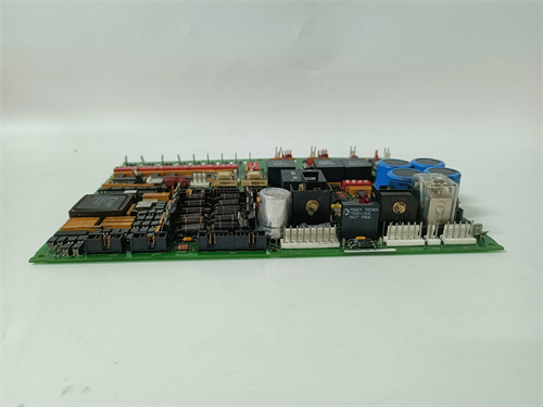
Type: Primary Power Supply Converter Board – 10A Continuous Output Version with active current sharing and redundant operation capability.
Compatibility: Exclusively designed for the GE Mark V Speedtronic series (firmware revisions R, S, and T). The DS200PCCAG10A is a direct replacement for the DS200PCCAG5 (5A version) and DS200PCCAG7 (7A version) in racks where higher current capacity is required, provided the backplane and cooling system can support the additional thermal load.
Input Voltage: Accepts a wide range of AC and DC inputs – 115 VAC ±10% at 47-63 Hz, or 125 VDC ±10% (nominal). The DS200PCCAG10A features automatic input detection and seamless transition between AC and DC sources, with prioritization favoring DC input when both are present to reduce harmonic distortion on the AC line.
Primary Outputs:
-
+5 VDC Logic Rail: 10A continuous, 12A peak (for 10-second transients) – the defining specification of the DS200PCCAG10A.
-
+15 VDC Analog Rail: 3A continuous, 4A peak.
-
-15 VDC Analog Rail: 2A continuous, 2.5A peak.
-
+24 VDC Field I/O Rail: 1.5A continuous (isolated).
Secondary Outputs (Auxiliary):
-
+3.3 VDC Standby: 0.5A continuous for wake-on-LAN and diagnostic keep-alive circuits (available even when main outputs are disabled by remote inhibit).
Efficiency: Greater than 85% at full load (10A on +5V rail), with power factor correction (PFC) achieving 0.99 typical – a significant improvement over earlier DS200PCCAG5 and DS200PCCAG7 boards which lacked PFC.
Connectors: Features a high-density 64-pin backplane connector (J1) for power delivery and status signaling, plus two 4-pin auxiliary terminals (TB1 and TB2) for external fault monitoring and remote voltage sense lines. The DS200PCCAG10A also includes a 6-pin programming header (J2) for firmware updates and configuration of current-sharing parameters.
Protection Features:
-
Overvoltage protection (OVP) on all outputs – latch-type, requires power cycle to reset.
-
Overcurrent protection (OCP) with foldback current limiting on +5V rail (limits to 11A in case of short circuit).
-
Overtemperature protection (OTP) – automatic shutdown at 85°C heatsink temperature, auto-restart when temperature drops below 70°C.
-
Input surge suppression – MOV and TVS diode array rated for 6 kV/3 kA transient immunity (IEC 61000-4-5 Level 4).
-
Reverse polarity protection on DC input.
Diagnostic Indicators: Six-LED status array – green “PWR OK” (+5V within tolerance), green “AC OK” (AC input present), green “DC OK” (DC input present), yellow “CUR LIM” (current limit active), red “FAULT” (internal failure or OVP/OTP triggered), and blue “SHARE” (active current sharing mode – indicates parallel operation with another DS200PCCAG10A).
Operating Temperature: 0°C to +50°C (ambient) with forced-air cooling (minimum 100 CFM). The DS200PCCAG10A incorporates a finned aluminum heatsink and two onboard temperature sensors (one on the main switching MOSFET, one on the output rectifier) for accurate thermal management.
Physical Dimensions: Standard 6U VME form factor (233mm x 160mm x 40mm depth), with a slightly taller heatsink than the DS200PCCAG5 – requires 1.5 slots of vertical clearance in the rack.
Weight: 1.8 kg (approx. 4.0 lbs) – heavier than lower-capacity versions due to the larger transformer and heatsink.
Advantages & Core Features
Unmatched 10A Current Capacity on +5V Rail
The DS200PCCAG10A delivers 10A continuous on the critical +5V logic rail, providing ample power for high-density processor configurations, such as dual DS200SLCCG1 communication boards and multiple DS200TCTGG1 I/O modules simultaneously. This capacity eliminates the voltage droop observed with the DS200PCCAG5 (5A) during turbine start-up transients, ensuring that logic circuits maintain proper voltage even when all I/O channels are active.
Active Current Sharing for Redundant Operation
The DS200PCCAG10A features an active current-sharing bus (accessible via the J1 backplane connector) that allows two identical boards to operate in parallel for N+1 redundancy. The boards automatically balance load current within ±5%, ensuring that no single unit exceeds 60% of its rated capacity under normal conditions. If one board fails, the remaining unit seamlessly absorbs the full load without voltage dip – a feature not available on the lower-cost DS200PCCAG5 or DS200PCCAG7 boards.
Wide Input Range with Automatic Source Selection
The DS200PCCAG10A accepts both 115 VAC and 125 VDC inputs simultaneously, with automatic prioritization of DC input to reduce AC line harmonics. If the DC source fails, the board transitions to AC within 1/2 cycle (8.3 ms at 60 Hz), maintaining output voltage within ±2% during the transfer. This dual-source capability makes the DS200PCCAG10A ideal for installations with battery-backed DC systems, where AC may be used only as a backup.
Power Factor Correction for Grid-Friendly Operation
Unlike earlier power boards, the DS200PCCAG10A includes active power factor correction (PFC), achieving a power factor of 0.99 across the full load range. This reduces harmonic currents drawn from the AC supply, preventing interference with sensitive instrumentation and meeting IEEE 519 harmonic distortion standards. For utility-scale power plants, this feature simplifies compliance with grid interconnection requirements.
Comprehensive Fault Diagnostics and Telemetry
The DS200PCCAG10A provides extensive diagnostic data through its backplane interface, including:
-
Real-time output current readback for each rail (accuracy ±2%)
-
Heatsink temperature and ambient temperature readings
-
Input voltage monitoring (both AC and DC)
-
Cumulative runtime hours and power-on cycle count
-
Fault history log (last 20 events stored in onboard EEPROM)
These data points are accessible through the Mark V controller’s diagnostic screens, enabling predictive maintenance and reducing unplanned outages.
Enhanced Thermal Management
The DS200PCCAG10A employs a dual-fan strategy: a primary 40mm fan mounted directly on the heatsink (variable speed based on temperature) and a secondary airflow channel that directs air across the input rectifier and transformer. The board’s thermal design maintains junction temperatures below 90°C even at 50°C ambient, ensuring long-term reliability. The overtemperature protection feature shuts down the board before any component reaches its maximum rated temperature (125°C), preventing catastrophic failure.
Remote Voltage Sense and Trim Capability
The DS200PCCAG10A includes remote voltage sense lines (TB1 terminals) that compensate for voltage drops across the backplane and cabling. This ensures that the +5V rail remains at exactly 5.00V ±1% at the load point, rather than at the board’s output terminals. Additionally, the board supports ±5% manual voltage trimming via an onboard potentiometer (R21), allowing fine-tuning for applications with unusual load requirements.
Application Cases in Field Use
High-Density Combined Cycle Plant: A 500 MW combined-cycle facility upgraded their Mark V system from DS200PCCAG5 boards to the DS200PCCAG10A after experiencing +5V rail drops (to 4.75V) during gas turbine start-up, causing intermittent processor resets. The 10A capacity of the DS200PCCAG10A eliminated the droop entirely, and the active current-sharing feature allowed them to run two boards in N+1 configuration, reducing the risk of single-point failure. Post-upgrade, the plant achieved 99.98% control system availability over a 12-month period.
Offshore Platform with UPS Integration: An offshore oil platform in the North Sea replaced failing DS200PCCAG7 boards with the DS200PCCAG10A to support a new 16-channel vibration monitoring system. The wide input range allowed the board to accept both AC from the platform’s diesel generator and DC from the emergency battery bank, ensuring uninterrupted operation during generator transfers. The board’s fault logging capability captured a gradual degradation of the DC rectifier, enabling proactive replacement before failure.
Nuclear Power Plant Safety System: A US nuclear facility used the DS200PCCAG10A in a redundant power supply configuration for their Mark V-based feedwater control system. The active current-sharing feature of the DS200PCCAG10A allowed both boards to operate at approximately 50% load each, with automatic failover. The board’s comprehensive diagnostics were integrated into the plant’s predictive maintenance program, with temperature and current trends monitored weekly to detect aging components early.
Industrial Gas Compressor Station: A natural gas pipeline compressor station deployed the DS200PCCAG10A to power multiple high-speed communication boards in a Mark V rack handling real-time SCADA data. The +5V rail’s 10A capacity supported six communication modules simultaneously, whereas the previous DS200PCCAG5 had been operating at 95% capacity, leading to occasional thermal shutdowns. The DS200PCCAG10A‘s PFC feature also eliminated harmonic interference that had been causing false readings on nearby flow meters.
Comparison with Competing / Replacement Products
| Feature | DS200PCCAG10A (GE Mark V) | DS200PCCAG5 (Lower-Capacity) | DS200PCCAG7 (Mid-Capacity) | Generic Third-Party Power Supply | GE Mark VIe Replacement Module |
|---|---|---|---|---|---|
| +5V Rail Capacity | 10A continuous (12A peak) | 5A continuous (6A peak) | 7A continuous (8.5A peak) | 5A typical (lab-rated, often overrated) | 10A continuous (requires new backplane) |
| Input Compatibility | 115VAC + 125VDC (dual, auto-select) | 115VAC only (no DC input) | 115VAC + 125VDC (manual select via jumper) | 110-240VAC only (no DC option) | 120-240VAC only (no DC option) |
| Power Factor Correction | Yes (0.99 PFC) | No (0.65 typical) | No (0.68 typical) | Often no PFC or lower quality | Yes (0.95) |
| Current Sharing | Active (±5% balance) – supports N+1 | None (single unit only) | None (single unit only) | None (cannot parallel) | Active (proprietary, not compatible) |
| Efficiency | >85% at full load | 78% typical | 80% typical | 82-88% claimed (varies widely) | >88% |
| Diagnostics | Full telemetry + 20-event log | LED-only (no telemetry) | LED-only (no telemetry) | LED-only or basic analog outputs | Full digital diagnostics (Ethernet) |
| Surge Protection | 6kV/3kA (Level 4) | 2kV/1kA (Level 2) | 2kV/1kA (Level 2) | 1-2kV typical (unspecified) | 4kV/2kA |
| Thermal Protection | OTP with auto-restart at 70°C | OTP with latch (requires manual reset) | OTP with latch (requires manual reset) | Varies – often thermal fuse (one-time) | OTP with auto-restart |
| Form Factor | 6U VME – 1.5-slot width | 6U VME – 1-slot width | 6U VME – 1-slot width | Requires custom bracket/adaptor | Different footprint – rack modification needed |
| Obsolescence Support | Rare – specialized high-capacity spare | Widely available as used/refurbished | Moderately available | Limited long-term reliability data | New but forces complete system overhaul |
| Typical Cost | High (specialized, limited supply) | Moderate | Moderate-high | Lower upfront, higher risk | Very high (requires new rack and cabling) |
Key Takeaway: The DS200PCCAG10A is the highest-capacity and most feature-rich power converter ever produced for the Mark V platform. Its 10A +5V capacity, dual-input support, active current sharing, PFC, and comprehensive diagnostics make it superior to all lower-capacity variants and generic alternatives. However, its specialized nature and physical size (1.5 slots) mean it requires careful planning for installation. For standard Mark V installations with typical I/O loads (under 5A total +5V draw), the DS200PCCAG5 or DS200PCCAG7 are more cost-effective. The DS200PCCAG10A is specifically justified for high-density or mission-critical applications where redundancy, capacity, and diagnostic visibility are paramount.
Selection Suggestions
Calculate Your +5V Load Accurately: The primary decision factor for selecting the DS200PCCAG10A is the total +5V current draw of your Mark V rack. Sum the +5V current requirements of all processor boards, I/O modules, and communication cards (values are listed in their respective datasheets). If the total exceeds 7A continuous or if your peak load exceeds 9A, the DS200PCCAG10A is the only safe option. If your total load is under 5A, the DS200PCCAG5 is sufficient. If between 5A and 7A, the DS200PCCAG7 is appropriate.
Evaluate Redundancy Requirements: If your turbine operation is mission-critical (e.g., nuclear, large utility, or offshore platform), consider using two DS200PCCAG10A boards in active current-sharing N+1 configuration. This ensures that a single board failure does not cause a system shutdown. The DS200PCCAG10A is the only Mark V power converter that supports this feature – the DS200PCCAG5 and DS200PCCAG7 cannot be paralleled.
Confirm Rack Slot Availability: The DS200PCCAG10A requires 1.5 slots of physical clearance due to its taller heatsink. Ensure your Mark V rack has a spare slot adjacent to the intended mounting location, and that the backplane has the necessary current-sharing bus traces. Consult your GE rack layout drawing (GEK-100376 series) to confirm slot compatibility.
Verify Cooling Capacity: The DS200PCCAG10A dissipates up to 60W at full load (compared to 35W for the DS200PCCAG5). Ensure your Mark V rack’s cooling fans provide at least 100 CFM airflow across the board. If you are upgrading from a lower-capacity board to the DS200PCCAG10A, you may need to upgrade the rack’s cooling system as well.
Assess Input Power Availability: The DS200PCCAG10A accepts both 115 VAC and 125 VDC. If your facility only provides AC power, the board works perfectly (with PFC benefits). If you have a DC battery system, the DS200PCCAG10A can prioritize DC for cleaner power and automatic transfer. However, if your facility only provides 230 VAC or 48 VDC, the DS200PCCAG10A is not compatible – you would need a different board or an external transformer.
Consider Future Expansion: If you anticipate adding more I/O modules or communication cards in the next 3-5 years, oversizing to the DS200PCCAG10A now can save you from a costly power upgrade later. The 10A capacity provides ample headroom for future growth, whereas the DS200PCCAG5 may become insufficient with just a few additional cards.
Procurement Strategy: The DS200PCCAG10A is one of the rarer Mark V spares due to its high capacity and specialized design. Only purchase from suppliers who can provide: (a) functional test reports including full-load burn-in (10A continuous for 24 hours), (b) ripple/noise measurements on all outputs, (c) thermal camera images to verify heatsink mounting, and (d) verification of current-sharing operation (if you plan to use two boards). Lead times can extend to 8-14 weeks for properly refurbished units. Avoid uncertified sellers offering “new old stock” – genuine NOS units are extremely rare and are often counterfeit or improperly stored.
Stock Spares: For critical installations using the DS200PCCAG10A, maintain at least one spare unit on-site. If you run a redundant N+1 configuration, you should have one additional spare (i.e., two operational + one spare = three total). Lead times for emergency replacements can exceed 12 weeks, so on-site stock is essential.
Important Precautions & Best Practices
Slot Selection and Mechanical Fit – The DS200PCCAG10A must be installed in a slot that provides sufficient clearance for the heatsink. Do not install it adjacent to another board in the neighboring slot without leaving a gap – the heatsink will mechanically interfere with the adjacent board’s components. Use slot positions with at least one empty slot on each side (e.g., slot 2 and slot 4 empty if installing in slot 3).
Always Power Down Completely – Before inserting or removing the DS200PCCAG10A, ensure the entire Mark V rack is de-energized and that the main input power is disconnected at the breaker. The board’s input capacitors (total 2,200 µF) can hold a dangerous charge for up to 5 minutes – wait at least that long before handling. Hot-swapping is not supported and will damage both the board and the backplane.
Proper Grounding – The DS200PCCAG10A requires a low-impedance ground connection through the backplane. Ensure that the backplane’s ground plane is properly bonded to the rack chassis. Floating grounds can cause erratic operation and may damage the onboard PFC circuitry. Measure ground continuity between the board’s mounting screws and the rack ground before applying power.
Input Source Sequencing – If you are using both AC and DC inputs, apply the DC source first (if available) and then the AC source. The DS200PCCAG10A automatically prioritizes DC, but if AC is already present when DC is applied, there may be a brief (2-3 ms) surge as the input selection switches. This surge is within specification but can be avoided by correct sequencing.
Output Capacitance Limits – The DS200PCCAG10A is designed for a maximum output capacitance of 10,000 µF on the +5V rail, 2,000 µF on the ±15V rails, and 1,000 µF on the +24V rail. Exceeding these values can cause instability during start-up and may trigger overcurrent protection. If your rack has large filter capacitors on the backplane, consult GE documentation to ensure they do not exceed these limits.
Remote Sense Wiring – If you use the remote sense feature (TB1 terminals), use twisted-pair wiring for the sense lines and route them away from high-current power conductors to avoid noise pickup. The sense lines must be connected to the load point (e.g., the backplane power distribution bus) and should be fused with 0.5A fuses to prevent short circuits from damaging the sense circuitry.
Temperature Monitoring – The DS200PCCAG10A‘s onboard temperature sensors provide critical data. Log these values regularly – a 5°C rise above baseline over time indicates heatsink degradation (dust accumulation) or fan failure. Clean the heatsink fins annually with compressed air (from the exhaust side to avoid pushing dust deeper) to maintain thermal performance.
Fan Replacement – The onboard 40mm fan has a rated lifespan of 40,000 hours (approx. 4.5 years). Replace the fan preventatively every 4 years, or when it begins to exhibit noise or vibration. Use only GE-specified fans with the correct airflow rating (7 CFM min at 50°C) and connector pinout. Aftermarket fans may have different electrical characteristics that could affect the board’s temperature sensing.
Fault Reset Procedure – If the DS200PCCAG10A enters a fault state (red FAULT LED illuminated):
-
Check input voltage – ensure AC is 103-127 VAC and DC is 112-138 VDC.
-
Check outputs for short circuits – use a multimeter to verify no dead shorts on any output rail.
-
Allow the board to cool for 10 minutes if overtemperature was suspected.
-
Cycle input power (disconnect both AC and DC, wait 30 seconds, then reapply) to reset latching faults.
-
If FAULT persists, the board requires repair or replacement – do not continue to reset repeatedly, as this may indicate a permanent internal failure.
Recalibration After Repair – If the DS200PCCAG10A is repaired (e.g., capacitor replacement or MOSFET replacement), it must be recalibrated using GE’s factory test fixture. This includes trimming the +5V rail to exactly 5.00V at the sense point, verifying OVP trip points, and testing current-sharing parameters. Do not accept a repaired board without a calibration certificate.
Storage – Store spare DS200PCCAG10A units in a climate-controlled environment at 10-30°C and 20-50% relative humidity. The electrolytic capacitors (particularly the large 2200 µF, 200V units) can degrade if stored above 40°C. Rotate stored spares every 24 months – install and run them for 24 hours at 50% load to reform the capacitors, then return to storage.
Final Expert Recommendation
The DS200PCCAG10A represents the ultimate power conversion solution for the GE Mark V platform, delivering exceptional 10A +5V capacity, dual-input redundancy, active current sharing, power factor correction, and comprehensive diagnostics that surpass all other Mark V power converter variants. Its 85% efficiency, 6 kV surge protection, and 0.99 power factor make it a robust choice for demanding power generation and industrial applications.
However, the DS200PCCAG10A is not a universal replacement. Its physical size (1.5 slots), higher cost, and specialized sourcing requirements mean it should be selected only when the application demands its unique capabilities. For standard Mark V installations with +5V loads under 5A, the DS200PCCAG5 remains the most cost-effective choice. For loads between 5A and 7A, the DS200PCCAG7 provides adequate capacity at moderate cost. The DS200PCCAG10A is specifically justified for high-density configurations, mission-critical systems requiring N+1 redundancy, facilities with both AC and DC power sources, and environments with stringent EMC requirements (e.g., near high-voltage switchgear).
When deploying the DS200PCCAG10A, thorough pre-installation planning is essential – verify slot availability, cooling capacity, input source compatibility, and total +5V load. If implementing current-sharing redundancy, ensure both boards are from the same manufacturing batch or have been matched for current-sharing parameters. Proper installation, periodic cleaning, and preventative fan replacement will maximize the board’s service life, which is rated at 15+ years in continuous operation.
For facilities still using the DS200PCCAG5 or DS200PCCAG7 and experiencing voltage droop, thermal shutdowns, or harmonic interference, the DS200PCCAG10A offers a proven upgrade path that addresses all these issues while providing future capacity for I/O expansion. Consult your GE Mark V system integrator to perform a load analysis and confirm compatibility before purchasing the DS200PCCAG10A – this investment will pay dividends in control system reliability, reduced maintenance interventions, and extended turbine availability.
GE DS303 A7A01LXA002XN
GE IS215ACLEH1A
A-B 1394-SJT22-T-RL
Tascam HS-8
.jpg)


Reviews
There are no reviews yet.