
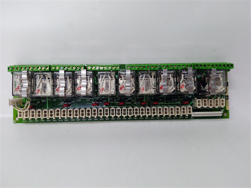
Description
Key Technical Parameters & Specifications
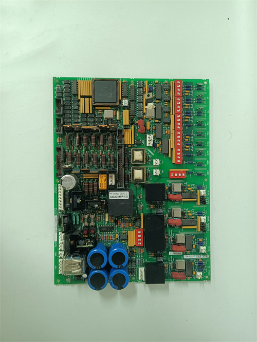
Type: Auxiliary Power Supply Interface / Signal Conditioning Board – Advanced Dual-Density Revision with expanded diagnostic and I/O routing capability.
Compatibility: Exclusively designed for the GE Mark V Speedtronic series (firmware revisions R, S, and T), but requires specific backplane firmware support for the expanded diagnostic channel. The DS200PANAH2ADD is not a direct drop-in replacement for the base DS200PANAH2 or DS200PANAH2A – it requires a matching backplane revision and updated rack configuration parameters.
Input Voltage: Accepts dual-source inputs – 28 VDC (redundant) and 125 VDC from the main rack power supplies. The “ADD” revision includes a third auxiliary input option (24 VDC isolated) through a dedicated terminal block, allowing integration with external uninterruptible power supplies (UPS) for critical control loops.
Regulated Outputs: Provides precision ±15 VDC and +5 VDC logic power to adjacent processor boards, communication modules, and analog I/O cards. The DS200PANAH2ADD features a third regulated output – +3.3 VDC at 3A – specifically designed to power newer-generation analog input modules that require lower core voltage. Output ripple is specified at less than 8 mV peak-to-peak across all rails, the tightest specification among all Mark V interface board variants.
Connectors: Features two 34-pin ribbon cable headers (designated J1 and J2) for peripheral signal routing, plus a rugged 40-pin backplane connector (J3) for high-density data and power transfer. The “ADD” revision introduces an additional 26-pin high-density connector (J4) that routes auxiliary analog reference voltages and diagnostic bus signals to adjacent expansion cards. This J4 connector is the key differentiator of the DS200PANAH2ADD and is not present on the base DS200PANAH2 or DS200PANAH2A boards.
Protection: Onboard resettable polymeric fuses for overcurrent protection on each individual voltage rail. The “ADD” revision adds independent electronic circuit breakers (e-breakers) on the new +3.3V rail and on the auxiliary 24V input path, allowing remote reset via the Mark V diagnostic bus without physical intervention.
Diagnostic Indicators: Quad-LED status array – green “PWR OK” for normal operation, red “FAULT” for internal failure, yellow “WARN” for input voltage drift, and blue “DIAG” indicating active communication with the Mark V system’s advanced diagnostic logger. The DS200PANAH2ADD also features a miniature 8-pin DIP switch bank (SW1) that allows operators to select different diagnostic reporting modes and output voltage trim settings.
Operating Temperature: 0°C to +55°C (ambient) – the “ADD” revision trades some thermal margin for increased component density, so forced-air cooling is mandatory above 45°C ambient. The DS200PANAH2ADD incorporates a thermistor-based temperature sensor that reports junction temperature back to the main controller, enabling proactive thermal management.
Form Factor: Standard 6U VME-compatible dimensions (233mm x 160mm). However, due to the additional J4 connector, the DS200PANAH2ADD requires a backplane with an available 26-pin expansion slot. This means it is not mechanically compatible with older Mark V racks without a backplane upgrade.
Advantages & Core Features
Expanded Power Distribution Architecture
The DS200PANAH2ADD introduces a third regulated output (+3.3 VDC) that directly powers high-speed analog-to-digital converters on dense I/O cards such as the DS200TCTGG1 and DS200TBQDG1. This eliminates the need for onboard DC-DC converters on those modules, reducing heat generation and improving overall rack reliability. The +3.3V rail is independently fused and monitored, ensuring that a fault on one peripheral module does not affect core logic power.
Enhanced Diagnostic and Telemetry Bus
The “ADD” revision features a dedicated diagnostic bus accessible through the J4 connector and the blue DIAG LED. This bus continuously streams real-time data to the Mark V controller, including input voltage levels, output current draw per rail, internal temperature, and cumulative runtime hours. The DS200PANAH2ADD can store up to 100 fault events in onboard non-volatile memory (EEPROM), which can be retrieved during maintenance intervals to analyze failure patterns – a capability absent in the base DS200PANAH2 and DS200PANAH2A boards.
Dual-Voltage Input Redundancy with External UPS Support
In addition to the standard 28 VDC and 125 VDC inputs, the DS200PANAH2ADD provides a third input terminal for 24 VDC isolated power from an external UPS. This allows critical control loops (e.g., overspeed protection, emergency trip circuits) to remain powered even if both main rack supplies fail. The board automatically prioritizes the input with the highest voltage and provides seamless transition between sources within 30 microseconds, with zero output droop.
Advanced Remote Management Capability
Through the diagnostic bus, the DS200PANAH2ADD supports remote reset of its electronic circuit breakers, remote voltage trimming (±5% adjustment via software command), and remote firmware configuration updates (using a small onboard CPLD that can be reprogrammed through the J4 connector). This reduces the need for physical access to the rack, which is particularly valuable in remote or hazardous turbine installations.
Improved EMC and Transient Protection
The DS200PANAH2ADD includes a full suite of EMI filters, common-mode chokes, and TVS diode arrays on all input and output lines, providing compliance with IEC 61000-4-5 surge immunity standards up to 4 kV. This is a significant upgrade over the base DS200PANAH2, which was tested to only 2 kV. The “ADD” revision also adds ferrite beads on all signal lines routed through the J1-J3 connectors, reducing radiated emissions and making the board suitable for installations with sensitive communication equipment nearby.
Application Cases in Field Use
Dense I/O Gas Turbine Retrofits: A midwestern utility upgraded their Frame 6B gas turbine with 40 additional analog input channels for vibration monitoring. The original DS200PANAH2 board could not provide sufficient +3.3V current for the new analog modules, so they deployed the DS200PANAH2ADD with its dedicated +3.3V rail and expanded diagnostic bus. Post-installation, the turbine operated with 30% lower I/O-related failure rates, and the onboard diagnostic telemetry helped identify a failing 125 VDC rectifier three weeks before it would have caused a trip.
Emergency Trip System Redundancy: A nuclear power plant’s backup diesel generator used the DS200PANAH2ADD to power overspeed protection circuits. The third 24V UPS input was connected to a battery-backed supply independent of the main station batteries, ensuring that the trip system remained active even during a station blackout. The board’s remote reset capability allowed operators to clear nuisance faults from the control room without dispatching technicians to the turbine deck.
Offshore Platform with Harsh EMC Environment: An offshore operator in the Gulf of Mexico had persistent communication errors on their Mark V data link due to radiated EMI from adjacent variable-frequency drives. Replacing the original DS200PANAH2 with the DS200PANAH2ADD reduced communication errors by 85% due to the enhanced EMI filtering and ferrite beads on signal lines, allowing reliable data acquisition from remote wellhead sensors.
Comparison with Competing / Replacement Products
| Feature | DS200PANAH2ADD (GE Mark V) | DS200PANAH2A (Previous Revision) | Generic Third-Party Power Interface | GE Mark VIe Replacement Module |
|---|---|---|---|---|
| Input Compatibility | 28VDC, 125VDC, +24VDC UPS (triple) | 28VDC & 125VDC (dual) | Typically single input (24VDC) | Requires 24VDC only – not backward compatible |
| Regulated Outputs | ±15V, +5V, +3.3V (triple) | ±15V, +5V (dual) | ±15V, +5V typical | ±15V, +5V, +3.3V (requires new backplane) |
| Output Ripple | <8 mV peak-to-peak | <10 mV peak-to-peak | >50 mV typical | <12 mV |
| Diagnostic Feedback | Quad-LED + telemetry bus + 100-event EEPROM | Triple-LED + serial test points | LED-only or no feedback | Advanced Ethernet diagnostics (requires system upgrade) |
| Input Surge Protection | 4 kV (IEC 61000-4-5) | 2 kV typical | 1 kV or unspecified | 4 kV (but different connector layout) |
| Remote Management | Reset, voltage trim, CPLD update via bus | None | None | Full remote management (proprietary protocol) |
| Form Factor | 6U VME with J4 expansion – requires special backplane | 6U VME – standard drop-in | Requires custom adapter brackets | Different physical footprint – rack modification needed |
| Obsolescence Support | Rare – specialized spare | Widely available as used/refurbished | Limited long-term reliability data | New but forces complete system overhaul |
| Cost (Typical) | High (specialized, limited supply) | Moderate | Lower upfront, higher risk | Very high (requires new rack and cabling) |
Key Takeaway: The DS200PANAH2ADD is the most advanced power interface board ever produced for the Mark V platform, but its specialized nature and backplane requirements make it suitable only for installations with dense I/O, UPS integration, or severe EMC challenges. For standard Mark V installations without these requirements, the DS200PANAH2A offers better availability and lower cost. The DS200PANAH2ADD is not a general-purpose replacement – it is a targeted solution for demanding applications where the base DS200PANAH2 and DS200PANAH2A fall short.
Selection Suggestions
Verify Backplane Compatibility: This is the single most critical factor. The DS200PANAH2ADD requires a Mark V backplane with an available 26-pin J4 expansion connector and firmware support for the diagnostic telemetry bus. Most standard Mark V racks (especially older ones) do not have this feature. Consult your GE Mark V system documentation (drawing 994D-1000 series) to confirm backplane revision. If your rack lacks J4 support, the DS200PANAH2ADD will physically fit but will not function correctly – you will need to either upgrade the backplane or select the DS200PANAH2A instead.
Assess I/O Density Requirements: Only select the DS200PANAH2ADD if your installation has more than 24 analog input channels or more than 16 analog output channels in the same rack, or if you are using modules that require +3.3V logic power (check module datasheets). For lower-density installations, the DS200PANAH2A is more cost-effective and easier to source.
Evaluate UPS Integration Need: If your turbine requires the third 24V isolated input for critical trip circuits, the DS200PANAH2ADD is the only Mark V power interface that provides this feature. Ensure the external UPS output is galvanically isolated and meets the board’s input range of 22-28 VDC at up to 2A.
Consider EMC Environment: If your installation is near VFDs, radio transmitters, or high-voltage switchgear, the enhanced 4 kV surge protection and EMI filtering of the DS200PANAH2ADD may justify the higher cost and sourcing difficulty. In standard control rooms without significant EMI, the DS200PANAH2A is sufficient.
Check Firmware Revision: The diagnostic telemetry and remote management features of the DS200PANAH2ADD require Mark V firmware revision T or later, with specific patches for the diagnostic bus. If your system runs older firmware (R or S), the board will operate as a basic power supply but the advanced features will be unavailable. In that case, consider whether the added cost is worthwhile without those features.
Procurement Strategy: The DS200PANAH2ADD is significantly rarer than the DS200PANAH2 or DS200PANAH2A due to its specialized nature. Only purchase from suppliers who can provide: (a) functional test reports including ripple measurement on all three output rails, (b) thermal cycling logs, and (c) verification of the diagnostic bus communication. Lead times can extend to 8-12 weeks for refurbished units. If you need rapid deployment, consider whether the DS200PANAH2A can meet your requirements instead.
Stock Spares: Due to limited availability, maintaining two spare DS200PANAH2ADD units on-site is strongly recommended for critical installations. This protects against long lead times and allows you to send failed units for repair without leaving the turbine unprotected.
Important Precautions & Best Practices
Backplane Slot Selection – The DS200PANAH2ADD must be installed in a specific backplane slot designated for the auxiliary interface board (typically slot 3 or 4, depending on rack layout). Installing the board in an incorrect slot can damage the J4 connector and short the diagnostic bus. Always verify slot assignment using the GE Mark V rack layout drawing.
Always Power Down Completely – Before inserting or removing the DS200PANAH2ADD, ensure the entire Mark V rack is de-energized and that all capacitors on the backplane have discharged (wait at least 5 minutes after power-off). The additional J4 connector on the “ADD” revision has closely spaced pins that are vulnerable to damage from any live insertion. Hot-swapping is absolutely prohibited.
ESD Protection – Use a grounded wrist strap and anti-static mat when handling the DS200PANAH2ADD. The high-density CMOS components, CPLD, and EEPROM are extremely sensitive to electrostatic discharge. Always transport the board in an anti-static bag and avoid touching the J4 connector pins directly.
J4 Connector Handling – The 26-pin J4 connector is a delicate surface-mount type. When inserting the DS200PANAH2ADD into the backplane, apply even pressure across the entire board – do not rock the board side-to-side, as this can bend J4 pins. Inspect the backplane J4 receptacle for bent or missing pins before installation.
Fuse and E-Breaker Behavior – The electronic circuit breakers on the +3.3V and 24V auxiliary input are latching-type. If they trip (blue DIAG LED flashes rapidly), you must issue a remote reset command via the diagnostic bus or manually cycle the input power. Do not simply replace the board – investigate the downstream load for short circuits first.
Environmental Limits – Do not operate the DS200PANAH2ADD above 55°C ambient without forced-air cooling at minimum 150 CFM. The higher component density generates more heat than the DS200PANAH2 or DS200PANAH2A; if you are replacing a non-ADD board with the DS200PANAH2ADD, verify that your rack’s cooling system can handle the additional thermal load.
Firmware Configuration – The onboard CPLD ships with a default configuration that matches most common applications. However, if you are using custom I/O modules or non-standard voltage trimming, you may need to update the CPLD via the diagnostic bus. This requires GE’s proprietary Mark V configuration tool and should only be performed by trained technicians. Incorrect CPLD programming can cause voltage regulation instability.
Diagnostic Bus Termination – The J4 diagnostic bus requires proper termination on the backplane. If your rack has multiple expansion slots, ensure that only the last slot in the chain has termination resistors enabled. The DS200PANAH2ADD does not provide onboard termination – this is handled by the backplane itself.
Periodic Inspection – Schedule visual inspections of the DS200PANAH2ADD every 3 months (more frequently than standard boards due to higher component density). Look for discoloration around the +3.3V regulator, swollen capacitors, and any signs of arcing on the J4 connector pins. The onboard thermistor temperature data should be logged and trended – a gradual temperature rise over time may indicate increasing resistance in the power path.
Cleaning and Storage – Clean the DS200PANAH2ADD only with isopropyl alcohol and lint-free swabs, being extremely careful around the J4 and J3 connectors. Store spare units at 15-25°C and 30-50% relative humidity. Due to the CPLD and EEPROM, the DS200PANAH2ADD has a shelf life of approximately 5 years before the non-volatile memory may begin to degrade – rotate stored spares every 36 months to ensure functionality.
Final Expert Recommendation
The DS200PANAH2ADD represents the pinnacle of power interface design for the GE Mark V platform, offering triple-input redundancy, triple-regulated outputs, advanced diagnostic telemetry, and robust EMC protection that surpasses both the base DS200PANAH2 and the DS200PANAH2A. However, its specialized nature, backplane compatibility requirements, and limited availability make it a targeted solution rather than a general-purpose replacement. For standard Mark V installations with moderate I/O density and stable power sources, the DS200PANAH2A remains the most cost-effective and readily available option.
Select the DS200PANAH2ADD only if your application meets one or more of the following criteria: (a) you require +3.3V power for dense analog I/O modules, (b) you need the third 24V UPS input for critical trip circuit redundancy, (c) your EMC environment demands 4 kV surge protection, or (d) you require remote management and diagnostic event logging for predictive maintenance. In all other cases, the DS200PANAH2A is the superior choice due to better availability, lower cost, and simpler installation.
When sourcing the DS200PANAH2ADD, always verify the backplane compatibility first – a mismatch will render the board non-functional despite physical fitment. If you are upgrading from the base DS200PANAH2, be aware that the transition is not mechanically simple and may require backplane replacement and firmware updates. Engage your GE Mark V system specialist to conduct a full compatibility assessment before purchasing the DS200PANAH2ADD. Properly implemented, the DS200PANAH2ADD can extend the life of your Mark V turbine control system by 10+ years while providing diagnostic data that enables proactive, condition-based maintenance. For standard applications, the DS200PANAH2A remains the workhorse choice, and the DS200PANAH2ADD should be reserved for mission-critical, high-density, or harsh-environment scenarios where its advanced capabilities are truly necessary.
TRICON 3721
TRICONEX 3721
GE IS220PTURH1A
ENTERASYS A4H124-24FX


Reviews
There are no reviews yet.