
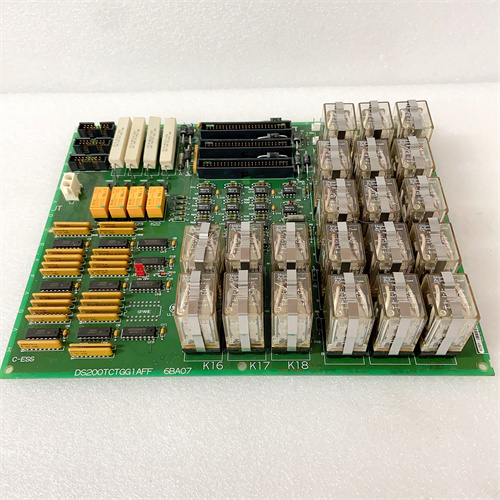
Description
Technical Parameters & Specifications
| Parameter | Specification |
|---|---|
| Manufacturer | General Electric (GE) |
| Series | Mark V Speedtronic |
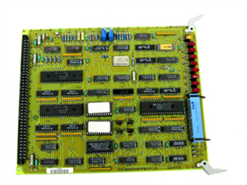
| Full Model | DS200DSFBG1A |
| Board Type | Digital Signal Feedback / Speed Processing Board |
| Input Channels | 3 dedicated speed sensor inputs (magnetic pickups) |
| Additional Inputs | 2 general-purpose pulse/frequency inputs (configurable) |
| Input Voltage Range | ±5V to ±50V AC (from MPU) |
| Frequency Range | 1 Hz to 20 kHz |
| Output Interface | Parallel VME backplane (digital speed data to CPM) |
| Accuracy | ±0.05% of reading over full range |
| Operating Temp | -30°C to +65°C |
| Protection | Conformal coating + gold-plated edge connectors |
| Physical Dimensions | 6U VME format (233mm × 160mm) |
| MTBF | > 140,000 hours |
Core Advantages & Key Features
-
High-Speed Signal Conditioning – The DS200DSFBG1A processes raw MPU signals with advanced filtering and zero-crossing detection, delivering clean digital frequency data even in the presence of electrical noise common in turbine environments.
-
Triple Redundant Speed Monitoring – Three dedicated input channels allow for 2-out-of-3 (2oo3) voting logic for overspeed protection, meeting stringent safety requirements for turbine control systems.
-
Automatic Threshold Adaptation – The board automatically adjusts to varying MPU signal amplitudes (from ±5V to ±50V) without manual gain adjustment, simplifying installation and maintenance.
-
Onboard Diagnostics – Six LEDs indicate channel status, signal presence, and communication health with the main processor.
-
Flexible Configuration – The two general-purpose pulse inputs can be configured for various applications including shaft position, gear tooth counting, or external frequency reference.
-
Isolated Inputs – Each speed channel is optically isolated from the backplane, protecting the main processor from field wiring faults or voltage spikes.
-
Plug-and-Play Compatibility – The DS200DSFBG1A integrates seamlessly with all Mark V main processors, including DS200CPCAG1A, and works alongside driver boards such as DS200DPCAG1ADC and DS200DPCAG1ADB without additional interface hardware.
Typical Applications
-
Gas Turbine Speed Sensing – Monitors turbine shaft speed via multiple MPUs for speed control and overspeed protection in GE 7FA and 9E turbines.
-
Steam Turbine Overspeed Protection – Provides critical speed feedback for overspeed trip systems, ensuring safe operation during load rejection events.
-
Compressor Shaft Speed Monitoring – Tracks high-speed compressor shaft RPM for performance monitoring and surge protection algorithms.
-
Geartooth Counting & Position Detection – The general-purpose inputs can count gear teeth for phase angle detection used in ignition timing or vibration analysis.
Field Example: A South American hydroelectric facility replaced obsolete speed monitoring modules with DS200DSFBG1A boards across 12 turbine units, achieving a 40% reduction in speed measurement jitter and eliminating nuisance overspeed trip events caused by noisy sensor signals.
Comparison: DS200DSFBG1A vs. Other Feedback Boards vs. Competitor
| Feature | DS200DSFBG1A | Alternative (Woodward 8440-2200) | Generic Tachometer Module |
|---|---|---|---|
| Primary Function | Digital speed feedback processing | Speed/frequency measurement | Speed measurement |
| Dedicated Speed Channels | 3 (with 2oo3 voting support) | 2 channels | 1–2 channels |
| General-Purpose Pulse Inputs | 2 (configurable) | None | None |
| Input Voltage Range | ±5V to ±50V AC (auto-ranging) | ±10V to ±40V (manual setting) | ±5V to ±30V (fixed) |
| Accuracy | ±0.05% | ±0.10% | ±0.20% |
| Hot-Swap Support | Yes | No | No |
| Diagnostic LEDs | 6 status LEDs | 2 status LEDs | 2–3 status LEDs |
| Conformal Coating | Yes (standard) | Optional (extra cost) | No |
| MTBF | > 140,000 hours | 100,000 hours | 80,000 hours |
Selection Guidelines & Precautions
-
Verify Sensor Compatibility – The DS200DSFBG1A accepts magnetic pickup (MPU) signals with amplitudes from ±5V to ±50V AC. For proximity probes with DC output, ensure proper signal conditioning or external converters are used.
-
Check Sensor Cable Quality – Use shielded twisted-pair cables for all speed sensor connections to minimize EMI pickup. Maximum recommended cable length is 300 meters for reliable signal integrity.
-
Grounding Practices – Proper grounding is critical for stable speed measurement. Connect cable shields to the designated ground terminal at the board end only, avoiding ground loops.
-
Configuration of General-Purpose Inputs – The two auxiliary pulse inputs can be configured via onboard jumpers for voltage level (5V, 12V, 24V) or current (NPN/PNP). Refer to GE manual GEK-119589 for detailed setting options.
-
Firmware Compatibility – When integrating the DS200DSFBG1A with a Mark V system, ensure the main processor firmware supports the board’s diagnostic handshake protocol. Compatibility is verified with DS200CPCAG1A revision 3.0 or higher.
-
Spare Parts Strategy – Maintain at least one DS200DSFBG1A as cold spare, particularly for critical speed protection applications. This board is not cross-compatible with earlier DS200DSFBG1 variants due to connector pinout differences.
Summary
The DS200DSFBG1A is a specialized digital signal feedback board for GE Mark V systems, providing high-accuracy speed monitoring with triple redundant channels for safety-critical overspeed protection. Its auto-ranging input capability, flexible general-purpose pulse inputs, and robust environmental protection make it ideal for gas turbines, steam turbines, and high-speed compressors. The board integrates seamlessly with DS200CPCAG1A processors and works alongside driver boards including DS200DPCAG1ADC and DS200DPCAG1ADB. Selection requires attention to sensor type, cable quality, proper grounding, and configuration of auxiliary inputs to ensure reliable speed feedback and system safety.
A-B 2711-K5A8
A-B 1756-ENBT
SHOWA SCM-DTU2
A-B 20G11ND011AA0NNNNN
.jpg)

Reviews
There are no reviews yet.