
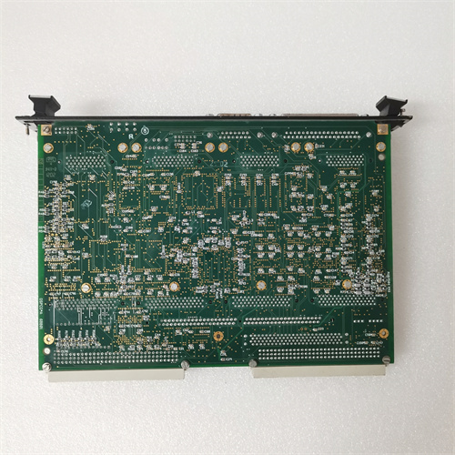
Description
Detailed Technical Parameters & Specifications
| Parameter | Specification |
|---|---|
| Manufacturer | General Electric (GE) |
| Series | Mark V Speedtronic |
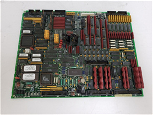
| Full Model Number | DS200DPCAG1ADB |
| Board Type | Driver / Power Supply Interface Card |
| Input Supply Voltage | 24 – 125 VDC (three isolated power inputs) |
| Analog Driver Outputs | 4 channels, configurable as ±10V voltage or 4–20mA current |
| Position Feedback Inputs | 2 channels, differential LVDT/RVDT interface with built-in excitation source |
| Digital I/O | 8 optically isolated inputs, 6 relay dry-contact outputs |
| Backplane Communication | Parallel VME bus (interfaces with main CPM processor) |
| Operating Temperature | -30°C to +65°C (industrial wide-temperature grade) |
| Protective Coating | Full-board conformal coating + gold-plated edge connectors |
| Physical Dimensions | 6U VME format (233mm × 160mm) |
These parameters confirm that the DS200DPCAG1ADB is not a general-purpose PLC module but a specialized board designed for high-reliability rotating machinery control. Its isolated power architecture and dual-channel redundant feedback design are fundamental to meeting SIL (Safety Integrity Level) requirements.
Core Advantages & Key Features
-
Hot-Swap Capability
The DS200DPCAG1ADB supports live insertion and removal while the system remains powered, eliminating the need for scheduled shutdowns during maintenance—a critical benefit for power plants and industrial facilities. -
Multi-Level Onboard Diagnostics
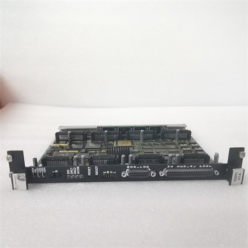
Six high-brightness LED indicators provide real-time status: main power good (PWR), backplane communication activity (COM), and overload/short-circuit alarms for each of the 4 drive channels (CH1–CH4). Maintenance personnel can quickly isolate faults to the board or channel level. -
Rugged Environmental Protection
Full conformal coating and thickened gold-plating on edge connectors ensure resistance to high humidity, salt spray, dust, and vibration—particularly valuable for offshore platforms, combined-cycle plants, and high-dust coal chemical environments. -
Flexible Field Configuration
Onboard DIP switches and jumper headers allow hardware-level configuration for each channel: output type (voltage or current), feedback sensor type (LVDT or RVDT), and filtering frequency. No external programming tool is required for basic setup. -
Traceable Firmware Revision
The ADB suffix clearly identifies the firmware revision level, enabling users to verify compatibility with GE upgrade bulletins and compare against newer or older variants such as DS200DPCAG1ADC or DS200DPCAG1ADD.
Typical Application Fields & Real-World Use Cases
The DS200DPCAG1ADB is predominantly deployed in the following high-value rotating machinery control systems:
-
Heavy-Duty Gas Turbines (e.g., GE 7FA, 9E series) – Controls inlet guide vanes (IGV) and fuel control servo valves, with response time requirements below 20ms.
-
Industrial Steam Turbines (e.g., GE D-11, D-20 series) – Drives governing valves and extraction control valves, receiving speed/load commands from the Mark V main processor (e.g., DS200CPCAG1A).
-
Compressor and Pump Anti-Surge Control – In natural gas pipeline booster stations, this board drives anti-surge valve servo actuators, ensuring the compressor avoids surge zones during rapid load fluctuations.
In a documented case study, a Southeast Asian combined-cycle plant experienced IGV response lag due to an aging driver board. After replacement with the DS200DPCAG1ADB, valve position tracking error improved from ±1.2% to ±0.3%, significantly enhancing combustion stability.
Comparison with Competing Products & Same-Series Variants
| Comparison Dimension | DS200DPCAG1ADB | Earlier Same-Series DS200DPCAG1A | Competitor (e.g., Woodward 5464 Series) |
|---|---|---|---|
| Number of Drive Channels | 4 channels | 2 channels | 4 channels |
| Feedback Input Type | Dual differential LVDT/RVDT with excitation | Single-ended LVDT | ±10V or 4–20mA only, no dedicated excitation source |
| Hot-Swap Support | Yes | Yes | No (requires power-off removal) |
| Firmware Upgrade Method | Online via backplane | EPROM chip replacement | Offline via dedicated programmer |
| Environmental Protection | Conformal coating + gold-plating | Gold-plating only (no coating) | Not available on most variants |
| GE Official Replaceability | Fully compatible with ADC/ADD later revisions | Discontinued, recommended upgrade to ADB | Requires complete re-design of wiring and configuration |
Compared to competitors, the DS200DPCAG1ADB offers the distinct advantage of full OEM lifecycle support and seamless backplane protocol compatibility with the Mark V system, eliminating the need for additional signal conditioners or protocol converters.
Selection Guidelines & Critical Precautions
-
Verify Firmware Compatibility
Before replacing or adding a DS200DPCAG1ADB, always check the firmware revision of the main processor (e.g., DS200CPCAG1A or DS200CPCAG2A). The ADB revision may have minor diagnostic instruction set differences compared to older main processors. Refer to GE Technical Information Letter (TIL) number GEK-119545 for specific compatibility matrices. -
Check Rack Slot Power Capacity
At full load driving four servo valves, the board can draw up to 28W peak power. Ensure the +24V and +125V power supply modules (e.g., DS200ADPAG1) in the corresponding backplane slot have sufficient margin to avoid voltage sag. -
Terminal Torque and Wire Gauge Requirements
Field wiring terminal blocks (TB1–TB4) recommend using AWG 18–22 shielded twisted-pair cables with a tightening torque of 0.56 – 0.79 N·m. Exceeding this torque may damage PCB solder pads or terminal blocks. -
Ambient Temperature and Cooling Planning
Although the operating temperature range is wide, if adjacent slots in the rack contain other high-power boards (e.g., DS200SDCCG1 communication card), forced air cooling or at least one empty slot for airflow is strongly recommended. -
Spare Parts Inventory Strategy
As the Mark V system has gradually entered its late-lifecycle phase, users are advised to keep at least one DS200DPCAG1ADB as a cold spare. Additionally, monitor GE announcements regarding Mark VIe upgrade paths and compatible adapter boards for future migration planning.
Summary
The DS200DPCAG1ADB is a technically mature and functionally complete driver interface board within the GE Mark V control system. With its isolated multi-channel drive capability, dual redundant feedback inputs, and rugged industrial design, it plays an irreplaceable role in gas/steam turbine and large compressor control. Proper selection requires careful attention to firmware matching, power supply headroom, and thermal conditions to ensure long-term reliable operation. For advanced diagnostic requirements or system upgrades, later revisions such as DS200DPCAG1ADD may be considered, but overall compatibility with the main processor and project cost must be thoroughly evaluated.
˹ MT125HU4DVE
A-B 1788-EN2DN
A-B 150-F25NBD
A-B 1746-NO8I



Reviews
There are no reviews yet.