
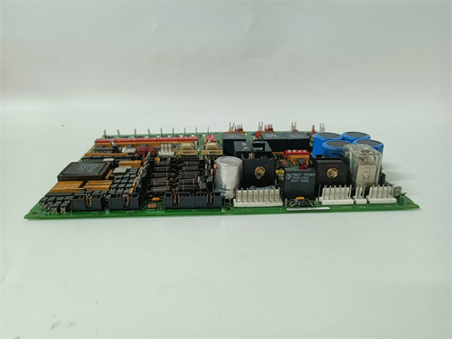
Description
Key Technical Parameters
| Parameter | Specification / Value |
|---|---|
| Manufacturer | General Electric (GE) |
| Series | Mark V Speedtronic™ |
| Board Type | Power Converter / Signal Conditioning Interface Board |
| Input Voltage | 120/240 V AC (single phase) or 125 V DC (nominal) |
| Output Rails | +5 V DC, ±15 V DC, +24 V DC (isolated) |
| Analog Input Channels | 8 differential inputs (0-10V, 4-20mA configurable) |
| Analog Output Channels | 4 isolated outputs (0-10V or 4-20mA) |
| Digital I/O | 16 optically isolated digital inputs, 8 relay outputs (2A, 250V AC) |
| Signal Scaling Accuracy | ±0.1% of full scale |
| Isolation Voltage | 2.5 kV RMS between power and logic sections |
| Operating Temperature | 0°C to +50°C (standard industrial range) |
| Mounting Type | VME-style 6U rack-mounted backplane connector |
| Protection Features | Overvoltage crowbar, overtemperature shutdown, short-circuit current limiting |
| Cooling | Passive heatsink with forced-air assist recommended |
Advantages & Key Features
The DS200DPCAG1 delivers several significant engineering advantages that make it essential for reliable turbine control system operation:
Integrated Power Conditioning: The DS200DPCAG1 consolidates multiple power conversion functions onto a single board, eliminating the need for separate power supplies and reducing cabinet space requirements. This integrated approach on the DS200DPCAG1 also simplifies wiring and improves overall system reliability by minimizing interconnect failure points.
Precision Signal Scaling: The DS200DPCAG1 features precision resistor networks and low-drift operational amplifiers that maintain better than 0.1% accuracy across the full operating temperature range. This ensures that the DS200DPCAG1 delivers accurate field current and voltage feedback to the main controller, enabling precise automatic voltage regulator (AVR) performance.
Galvanic Isolation Architecture: The DS200DPCAG1 employs transformer-based isolation between the power input stage and all logic-side circuits. This allows the DS200DPCAG1 to interface safely with high-voltage field circuits while protecting the sensitive Mark V processor from potential ground loops or fault currents.
Comprehensive Protection Suite: The DS200DPCAG1 integrates multiple protection layers including overvoltage crowbar circuits, fast-acting current limiters, and thermal shutdown with hysteresis. If any parameter exceeds safe limits, the DS200DPCAG1 autonomously disables its outputs and generates a fault signal to the main controller before damage can occur.
Flexible I/O Configuration: The DS200DPCAG1 provides jumper-selectable options for each analog input and output channel, allowing the DS200DPCAG1 to accommodate various transducer types (voltage, current, RTD, thermocouple) without requiring external signal conditioners.
Diagnostic LED Indicators: The DS200DPCAG1 features a comprehensive array of status LEDs that provide immediate visual indication of input power status, output rail health, communication activity, and fault conditions, enabling rapid troubleshooting during maintenance.
Application Cases in Key Industries
The DS200DPCAG1 is deployed across a wide range of power generation and heavy industrial applications where reliable power conversion and signal conditioning are essential:
Gas Turbine Combined Cycle Plants: The DS200DPCAG1 provides regulated power for the excitation control electronics and conditions the feedback signals from the generator’s voltage transformers and current transformers. In these applications, the DS200DPCAG1 ensures that the AVR receives accurate synchronization and voltage regulation data.
Steam Turbine Generator Excitation Systems: In large thermal power plants, the DS200DPCAG1 powers the digital excitation controller and scales the field voltage and current signals. The precision scaling capabilities of the DS200DPCAG1 directly impact the stability of the generator’s terminal voltage during grid disturbances.
Emergency Diesel Generator Controls: The DS200DPCAG1 is used in nuclear and critical facility backup power systems where the DS200DPCAG1 provides power conditioning and signal interface for the generator’s voltage regulator, ensuring rapid response during black-start scenarios.
Industrial Cogeneration Systems: In steel mills, refineries, and chemical plants with on-site power generation, the DS200DPCAG1 interfaces the turbine control system with the plant’s DCS (Distributed Control System), providing scaled analog signals representing real-time generation parameters.
Hydroelectric Synchronous Condenser Applications: The DS200DPCAG1 conditions signals for static excitation systems in hydro plants operating in synchronous condenser mode, where precise reactive power control is essential for grid voltage support.
Comparison with Competing Products
When evaluated against similar power interface boards from ABB (PCD232A) and Siemens (SIMADYN D 6DD1680-0BA0), the DS200DPCAG1 demonstrates specific strengths and limitations:
Power Conversion Integration: The DS200DPCAG1 integrates power conversion, signal scaling, and digital I/O on a single board, whereas ABB’s offering requires separate power supply and I/O modules, and Siemens provides a modular approach with separate cards for each function.
Isolation Voltage Rating: The DS200DPCAG1 offers 2.5kV isolation, comparable to ABB’s 2.5kV but exceeding Siemens’s 1.5kV rating. This makes the DS200DPCAG1 better suited for high-voltage field applications.
Scaling Accuracy: The DS200DPCAG1 achieves ±0.1% accuracy, matching Siemens’s specification and exceeding ABB’s ±0.25% rating. The DS200DPCAG1 delivers superior performance for precision AVR applications.
Protection Features: The DS200DPCAG1 includes comprehensive overvoltage crowbar and thermal protection, while ABB offers only basic overcurrent protection and Siemens provides moderate protection features. The DS200DPCAG1 provides the most robust protection suite among the three.
Backward Compatibility: The DS200DPCAG1 is a direct drop-in replacement for earlier GE DPC variants, while ABB and Siemens boards require adapter plates and wiring modifications for installation in Mark V cabinets.
Availability: The DS200DPCAG1 is actively supported through GE’s legacy parts network and third-party vendors, while ABB and Siemens maintain active production with varying lead times.
Key Differentiator: The DS200DPCAG1 uniquely combines high-precision signal scaling (±0.1%) with comprehensive integrated protection features and galvanic isolation in a single board that remains fully compatible with existing Mark V installations. No competing product offers this exact combination of integration, accuracy, and protection in a drop-in compatible format, making the DS200DPCAG1 the preferred choice for Mark V system upgrades and replacements where preserving existing cabinet wiring is essential.
Selection Suggestions & Purchasing Precautions
When procuring or specifying a DS200DPCAG1, consider the following expert guidelines:
Verify Input Voltage Configuration: The DS200DPCAG1 is available with different input voltage configurations. Confirm your plant’s auxiliary supply voltage (120V AC, 240V AC, or 125V DC) matches the DS200DPCAG1 you are ordering. Incorrect input voltage selection on the DS200DPCAG1 will result in immediate damage upon power application.
Check Output Rail Tolerances: The DS200DPCAG1 provides multiple regulated output rails. If your downstream electronics require tighter tolerances than the DS200DPCAG1 standard specification (±5%), request the precision option which provides ±2% regulation on critical rails.
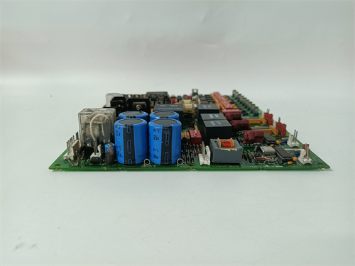
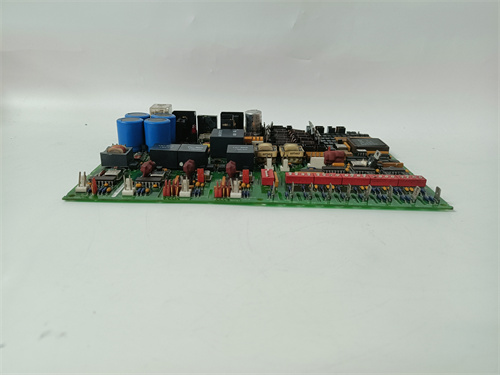
Inspect All Connectors Thoroughly: The DS200DPCAG1 has multiple high-current and signal connectors. Before installation, inspect all pins on the DS200DPCAG1 for bending, corrosion, or solder joint cracking. The power connectors on the DS200DPCAG1 are particularly susceptible to thermal stress after years of service.
Evaluate Capacitor Age: For refurbished DS200DPCAG1 units, request the manufacturing date code. The large electrolytic capacitors in the power conversion section of the DS200DPCAG1 have a typical service life of 10-15 years. If the DS200DPCAG1 you receive exceeds this age, consider proactive capacitor replacement before installation.
Verify Analog Calibration Records: The DS200DPCAG1 should be accompanied by a calibration certificate showing factory scaling accuracy. If the DS200DPCAG1 lacks current calibration documentation, plan for bench calibration before installation to ensure accurate feedback signals.
Document Wiring Connections: Before removing an existing DS200DPCAG1, document all field wiring connections to the board’s terminal blocks. The DS200DPCAG1 has multiple field connections that must be reconnected identically on the replacement unit to maintain proper system operation.
Critical Safety & Operational Precautions
High Voltage Exposure Hazard: The DS200DPCAG1 operates with input voltages up to 240V AC and generates output rails that may be present even when the board appears inactive. Always de-energize the entire control cabinet and wait at least five minutes for the DS200DPCAG1 to discharge its internal capacitors before handling or connecting field wiring. The DS200DPCAG1 uses large filter capacitors that retain dangerous charge after power removal.
Capacitor Discharge Verification: After de-energizing, use a voltmeter to verify that all capacitors on the DS200DPCAG1 have discharged below 5V before touching any conductive surfaces. The primary filter capacitors on the DS200DPCAG1 can hold charge for several minutes depending on bleeder resistor condition.
Ground Integrity Mandatory: The DS200DPCAG1 relies on a low-impedance chassis ground for both safety and proper noise suppression. Before applying power, measure the resistance between the DS200DPCAG1 mounting ears and the cabinet ground bus. This resistance must be less than 0.1 ohm. A poor ground connection to the DS200DPCAG1 can cause erratic signal scaling, false fault indications, and potential shock hazards.
Electrostatic Discharge (ESD) Protection: Despite the DS200DPCAG1 having a robust power stage, the signal conditioning and logic sections remain ESD-sensitive. Use grounded wrist straps and ESD-safe work surfaces when handling the DS200DPCAG1 outside the rack.
Thermal Management Planning: The DS200DPCAG1 dissipates significant power (typically 25-40W) depending on the output load. Ensure that the DS200DPCAG1 is installed in a rack location with adequate airflow. If the DS200DPCAG1 must be installed in a low-airflow area, consider adding a dedicated cooling fan or heat sink extension to prevent overtemperature shutdown.
Input Power Quality Verification: Before applying power to a new DS200DPCAG1, verify that the incoming auxiliary supply is within specified limits (voltage, frequency, and distortion). The DS200DPCAG1 includes protection circuitry, but sustained overvoltage or severe waveform distortion can degrade the board’s reliability over time.
Fuse Rating Confirmation: The DS200DPCAG1 uses internal and external fuses for protection. Verify that the external fuse rating matches the DS200DPCAG1 specification (typically 3-5A slow-blow depending on input voltage). Using an incorrect fuse rating on the DS200DPCAG1 will either offer inadequate protection or cause nuisance trips during normal startup current surges.
Post-Installation Signal Verification: After installing a replacement DS200DPCAG1, perform a systematic verification of all input and output signals. Inject known test signals to each analog input of the DS200DPCAG1 and verify the corresponding scaled output matches the expected value within specification. Monitor all output rails of the DS200DPCAG1 under load to confirm proper regulation. Only after this verification should the DS200DPCAG1 be placed into full operational service with the turbine running.
Periodic Calibration Check: For mission-critical applications, plan periodic calibration checks of the DS200DPCAG1 at least once per year or per the plant’s maintenance schedule. The precision scaling networks on the DS200DPCAG1 can drift over time due to component aging, particularly in high-temperature environments. Recalibration of the DS200DPCAG1 ensures continued AVR accuracy and system stability.
GE IC200CPUE05
HIKSCH MANN RH1-TP/FL
B&R ECE243-0
SIEMENS 6SN1123-1AA00-0CA2


Reviews
There are no reviews yet.