
Description
Technical Parameters
-
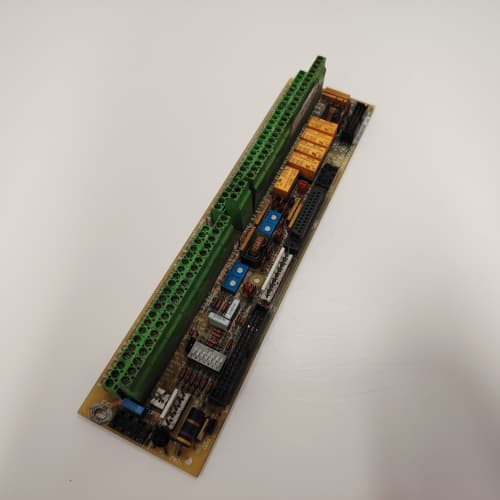
Product Type: Digital I/O interface board
-
Digital inputs: 6 (24 VDC, opto-isolated, sinking/sourcing selectable)
-
Digital outputs: 4 (24 VDC, 0.5A, short-circuit protected, opto-isolated)
-
Input voltage: 24 VDC (±10%)
-
Output rating: 0.5A per channel (resistive), 0.2A (inductive)
-
Response time: <5 ms (inputs), <2 ms (outputs)
-
Diagnostics: Input/output status, short-circuit detection (outputs)
-
Isolation: 2500 Vrms between I/O and drive logic
-
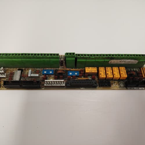
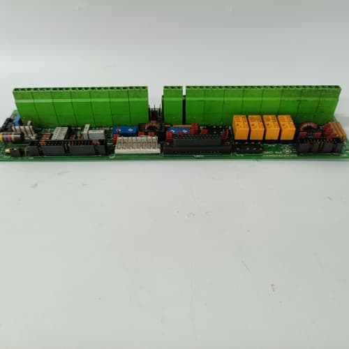
Terminal type: Screw-type (24–12 AWG) – secure for high vibration
-
Connectors: One 26-pin header to regulator board; one 10-position terminal block
-
Mounting: 4× M4 holes (standard GE rack footprint)
-
Power supply: +5 VDC and +15 VDC from regulator board
-
Operating temperature: -20°C to 65°C (extended)
-
Conformal coating: Marine-grade (moisture and corrosion resistant) – AAG1 specific
-
LED indicators: Power, Fault, and per-channel I/O status
Advantages & Features
-
Opto-isolated I/O – Galvanic isolation on all I/O points on GE 531X213D10AAG1 protects the regulator board from field wiring faults
-
Short-circuit protection – Digital outputs on GE 531X213D10AAG1 are protected against shorts and overcurrent
-
Flexible input wiring – Sinking or sourcing configuration on GE 531X213D10AAG1 via jumpers for compatibility with various sensors
-
Marine-grade conformal coating – Protects GE 531X213D10AAG1 from humidity, salt spray, and corrosive gases
-
Screw terminals – Secure connections on GE 531X213D10AAG1 resist loosening from vibration
-
Per-channel diagnostic LEDs – Individual I/O status LEDs simplify troubleshooting
-
Extended temperature range – -20°C to 65°C for harsh environments
-
Plug-and-play – Direct replacement for earlier D10 revisions
Application Cases
-
Conveyor control – Material handling system used GE 531X213D10AAG1 to read 6 photoeye inputs and control 4 motor contactor outputs on an AC-300 drive
-
Offshore platform – Corrosive environment used GE 531X213D10AAG1 for pump status monitoring; conformal coating prevented salt spray damage
-
Mining equipment – High-vibration environment used GE 531X213D10AAG1; screw terminals maintained secure connections
Competitive Comparison
| Aspect | GE 531X213D10AAG1 (OEM) | Generic Aftermarket Digital I/O Board |
|---|---|---|
| I/O points | 6 inputs / 4 outputs | Typically fewer |
| Output protection | Short-circuit + overcurrent | Limited or none |
| Input flexibility | Sinking/sourcing selectable | Fixed (one type) |
| Conformal coating | Marine-grade | None |
| Terminals | Screw (vibration-proof) | Spring-clamp or screw |
| Temperature range | -20°C to 65°C | 0°C to 50°C typical |
Selection Suggestions
-
Choose GE 531X213D10AAG1 for applications requiring 6 digital inputs and 4 digital outputs with harsh environment protection
-
Verify your input devices (sensors, switches) are 24 VDC compatible – GE 531X213D10AAG1 inputs are designed for 24 VDC
-
Verify sinking/sourcing configuration – set via jumpers on GE 531X213D10AAG1 to match your sensors
-
Do not exceed 0.5A on digital outputs – use interposing relays for higher current loads on GE 531X213D10AAG1
-
Verify field wiring is within 24–12 AWG range for screw terminals
-
Confirm regulator board compatibility – works with 531X111, 531X139, and 531X305 series
-
Prefer remanufactured units with new optocouplers, terminals tested, and coating intact
Precautions
-
Disconnect power before handling GE 531X213D10AAG1 – field wiring may carry external voltages
-
Do not exceed 24 VDC on inputs – higher voltage damages the optocouplers
-
Do not exceed 0.5A on outputs – use interposing relays for higher current loads
-
For inductive loads (relays, solenoids), use external flyback diodes across the load to protect GE 531X213D10AAG1 outputs
-
Verify input wiring polarity – reverse polarity may damage the optocouplers on GE 531X213D10AAG1
-
Torque terminal screws to 0.5–0.6 N·m – over-tightening strips threads; under-tightening causes loose connections
-
Torque mounting screws to 2–3 N·m – over-tightening cracks the PCB
-
Inspect conformal coating for scratches or cracks before installation – damaged coating exposes the PCB to corrosion
-
If a channel’s LED is off, check field wiring and power supply first
-
Store spare boards in ESD-safe packaging – optocouplers are sensitive to static discharge
YASKAWA CIMR-JB2A0006
ABB DCS-CP-P
FANUC A06B-0117-B855#0049
A-B 1769-IF4

.jpg)

Reviews
There are no reviews yet.