
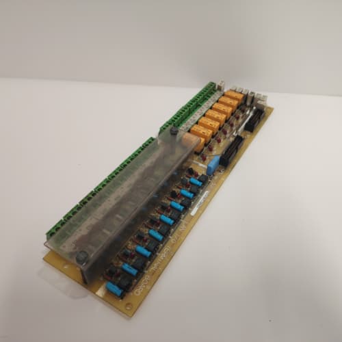
Description
Technical Parameters
-
Product Type: Keypad / display interface board
-
Interface: Serial link to regulator board (proprietary GE protocol)
-
Display support: Alphanumeric and graphic keypads
-
Keypad connector: 10-pin ribbon cable (or 26-pin pass-through)
-
Communication speed: Enhanced (ADG1 – reduced polling lag)
-
Diagnostic memory: Expanded – stores keypad/communication fault history (ADG1 specific)
-
Diagnostics: Keypad status, communication error detection, fault logging
-
Power supply: +5 VDC from regulator board (200 mA max)
-
Terminal type: Spring-clamp (24–16 AWG) – fast installation
-
Connectors: One 26-pin header to regulator board; one 10-pin keypad connector; one 6-pin terminal block
-
Mounting: 4× M4 holes (standard GE rack footprint)
-
Operating temperature: -20°C to 65°C (extended)
-
Conformal coating: Marine-grade (moisture and corrosion resistant) – ADG1 specific
-
LED indicators: Power, Communication Activity, Fault, Memory Status
Advantages & Features
-
Enhanced display driver – Supports newer/larger GE keypads on GE 531X211KLDADG1
-
Expanded diagnostic memory – Stores fault history on GE 531X211KLDADG1 for troubleshooting intermittent keypad/communication issues
-
Spring-clamp terminals – Faster wiring on GE 531X211KLDADG1 reduces installation time for auxiliary connections
-
Faster communication – Reduced keypad response lag for parameter navigation on GE 531X211KLDADG1
-
Extended temperature range – -20°C to 65°C for harsh environments
-
Marine-grade conformal coating – Protects GE 531X211KLDADG1 from humidity, salt spray, and corrosive gases
-
Memory Status LED – Indicates fault log storage/retrieval activity
-
Diagnostic LEDs – Communication activity and fault indicators for rapid troubleshooting
-
Plug-and-play – Direct replacement for earlier KLD revisions; no configuration changes needed
Application Cases
-
Large-scale retrofit – System integrator used spring-clamp terminals on GE 531X211KLDADG1 for 20 drive keypad installations, reducing wiring time by 30%; diagnostic memory helped identify intermittent keypad communication faults
-
Offshore platform – Corrosive environment used GE 531X211KLDADG1 for keypad interface; conformal coating prevented salt spray damage; fault logging enabled predictive maintenance
-
Cold storage – Freezer facility (-15°C) used GE 531X211KLDADG1 for reliable keypad operation in low temperatures; diagnostic memory tracked communication errors
Competitive Comparison
| Aspect | GE 531X211KLDADG1 (OEM) | Generic Replacement Keypad Board |
|---|---|---|
| Display support | Alphanumeric + graphic | Alphanumeric only |
| Diagnostic memory | Yes (fault logging) | None |
| Terminals | Spring-clamp (fast) | Screw or none |
| Communication speed | Fast (ADG1 enhanced) | Standard (slower) |
| Conformal coating | Marine-grade | None |
| Temperature range | -20°C to 65°C | 0°C to 50°C typical |
Selection Suggestions
-
Choose GE 531X211KLDADG1 for keypad upgrades, large-scale retrofits requiring fast wiring, harsh/corrosive environments, and diagnostic memory for troubleshooting
-
Verify keypad connector type (10-pin ribbon) matches your keypad
-
Verify auxiliary wiring is within 24–16 AWG range for spring-clamp terminals on GE 531X211KLDADG1
-
Confirm regulator board compatibility – works with 531X111, 531X139, and 531X305 series
-
Prefer remanufactured units with new display driver ICs, capacitors, terminals tested, memory ICs verified, and coating intact
Precautions
-
Disconnect power before handling GE 531X211KLDADG1
-
For stranded wires on spring-clamp terminals, use ferrules to prevent strand fraying
-
Insert wires fully until the wire stop is reached – partially inserted wires cause intermittent connections
-
Use anti-static handling – driver ICs and memory ICs are ESD-sensitive
-
When replacing, ensure the keypad cable is correctly seated – misalignment causes communication errors
-
Verify keypad model compatibility – some newer keypads require ADG1 or later
-
Fault history on GE 531X211KLDADG1 can be accessed via drive interface – consult manual for retrieval
-
Torque mounting screws to 2–3 N·m – over-tightening cracks the PCB
-
Inspect conformal coating for scratches or cracks before installation – damaged coating exposes the PCB to corrosion
-
If the “Fault” LED illuminates, check the keypad cable connection first
-
Store spare boards in ESD-safe packaging
A-B 1746-NI8
A-B 1746-NI8
AB 1794-IE12
SCHNEIDER 140NOE77101
.jpg)


Reviews
There are no reviews yet.