
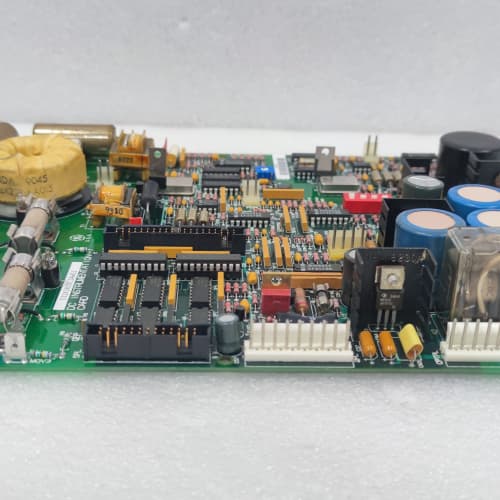
Description
Technical Parameters
-
Product Type: Remote terminal / I/O interface board
-
Digital inputs: 8 (24 VDC, opto-isolated)
-
Digital outputs: 8 (24 VDC, 0.5A, short-circuit protected)
-
Analog inputs: 4 (0–10V, 0–20mA, 4–20mA, selectable)
-
Analog outputs: 2 (0–10V or 4–20mA, 12-bit resolution)
-
Communication: Serial link to regulator board (proprietary GE protocol) – expanded buffer
-
Transient protection: Enhanced TVS diodes on all I/O points (AHG4 specific)
-
Diagnostic memory: Expanded – stores detailed fault history (AHG4 specific)
-
Diagnostics: Input/output status, communication error detection, enhanced fault logging
-
Terminal type: Screw-type (24–12 AWG) – secure for high vibration
-
Isolation: 2500 Vrms between I/O and drive logic
-
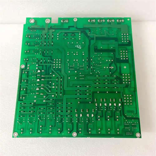
Connectors: One 26-pin header to regulator board; one 20-position terminal block for field wiring
-
Mounting: 4× M4 holes (standard GE rack footprint)
-
Power supply: +5 VDC and +15 VDC from regulator board
-
Operating temperature: -20°C to 70°C (extended)
-
Conformal coating: Marine-grade (moisture and corrosion resistant) – AHG4 specific
-
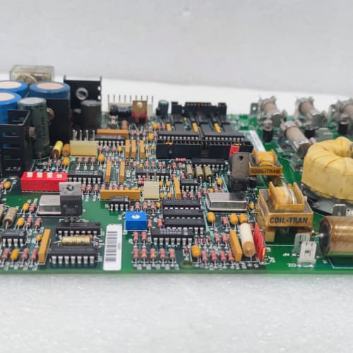
LED indicators: Power, Fault, Communication, Memory Status, and per-point I/O status
Advantages & Features
-
Multi-function I/O – 8 digital inputs, 8 digital outputs, 4 analog inputs, and 2 analog outputs on GE 531X191RTBAHG4 provide comprehensive remote I/O capability
-
Screw terminals – Secure connections on GE 531X191RTBAHG4 resist loosening from vibration (mobile, mining, marine)
-
Expanded communication buffer – Faster data exchange on GE 531X191RTBAHG4 reduces communication delays for critical I/O
-
Enhanced diagnostic memory – Stores detailed fault history on GE 531X191RTBAHG4 with more event records for troubleshooting
-
Enhanced transient protection – TVS diodes on all I/O points protect GE 531X191RTBAHG4 from voltage spikes
-
Marine-grade conformal coating – Protects GE 531X191RTBAHG4 from humidity, salt spray, and corrosive gases
-
Per-point diagnostic LEDs – Individual I/O status LEDs simplify troubleshooting
-
Memory Status LED – Indicates fault log storage/retrieval activity
-
Short-circuit protection – Digital outputs are protected against shorts and overcurrent
-
Galvanic isolation – 2500 Vrms protects regulator board from field wiring faults
-
Extended temperature range – -20°C to 70°C for harsh environments
-
Plug-and-play – Direct replacement for earlier RTB revisions
Application Cases
-
Mining conveyor – High-vibration environment used GE 531X191RTBAHG4 for remote conveyor control; screw terminals maintained secure connections; enhanced diagnostic memory helped identify intermittent sensor faults with detailed event records
-
Offshore platform – Corrosive environment used GE 531X191RTBAHG4 for remote pump control; conformal coating prevented salt spray damage; transient protection handled lightning surges
-
Mobile equipment – Used GE 531X191RTBAHG4 for remote I/O on a crane; screw terminals resisted loosening from vibration; enhanced fault logging tracked intermittent I/O issues
Competitive Comparison
| Aspect | GE 531X191RTBAHG4 (OEM) | Generic Aftermarket Remote I/O Board |
|---|---|---|
| I/O points | 8 DI / 8 DO / 4 AI / 2 AO | Limited (typically fewer points) |
| Terminals | Screw (vibration-proof) | Spring-clamp or screw |
| Communication buffer | Expanded (fast) | Standard (slower) |
| Diagnostic memory | Enhanced (detailed logging) | None or basic |
| Transient protection | Yes (TVS on all I/O) | Basic or none |
| Conformal coating | Marine-grade | None |
| Diagnostics | Per-point LEDs + enhanced memory | Limited or none |
| Isolation | 2500 Vrms | 1500 Vrms typical |
| Temperature range | -20°C to 70°C | 0°C to 50°C typical |
Selection Suggestions
-
Choose GE 531X191RTBAHG4 for high-vibration environments (mobile, mining, marine) requiring comprehensive remote I/O, fast communication, transient protection, and enhanced diagnostic memory for detailed troubleshooting
-
Verify your field I/O requirements – GE 531X191RTBAHG4 provides 8/8/4/2 points
-
For analog inputs, verify signal type (voltage/current) – configure via jumpers
-
For analog outputs, verify signal type (voltage/current) – configure via jumpers
-
Verify field wiring is within 24–12 AWG range for screw terminals
-
Confirm regulator board compatibility – works with 531X111, 531X139, and 531X305 series (firmware must support RTB)
-
Prefer remanufactured units with new optocouplers, terminals tested, buffer ICs verified, memory ICs tested, transient protection verified, and coating intact
Precautions
-
Disconnect power before handling GE 531X191RTBAHG4 – field wiring may carry external voltages
-
The enhanced transient protection protects the board but does not eliminate the need for external surge suppressors on long cable runs
-
Do not exceed 0.5A on digital outputs – use interposing relays for higher current loads
-
For analog inputs in current mode, ensure internal resistors are selected via jumpers on GE 531X191RTBAHG4
-
Use shielded twisted-pair cables for analog signals – unshielded cables pick up EMI from VFD output
-
Keep I/O cables separated from motor power leads (minimum 30 cm) to avoid EMI-induced errors
-
Torque terminal screws to 0.5–0.6 N·m – over-tightening strips threads; under-tightening causes loose connections
-
Torque mounting screws to 2–3 N·m – over-tightening cracks the PCB
-
Inspect conformal coating for scratches or cracks before installation – damaged coating exposes the PCB to corrosion
-
If a channel’s LED is off, check field wiring and power supply first
-
Enhanced fault history on GE 531X191RTBAHG4 can be accessed via drive interface – consult manual for retrieval and interpretation
-
Test analog inputs/outputs with known signals after installation to verify scaling
-
Store spare boards in ESD-safe packaging
A-B 1756-OB32
GE IC200UDR005
GE D20C PANEL
.jpg)

Reviews
There are no reviews yet.