
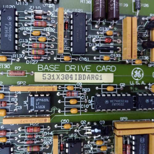
Description
Technical Parameters
-
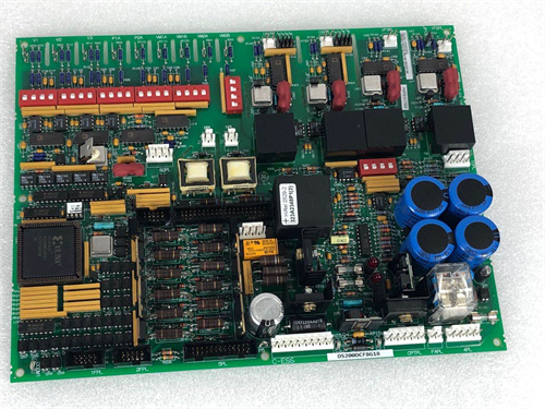
Product Type: Safety / stop interface board
-
Safety inputs: 2 channels (redundant – for E-stop and enable circuits) – 24 VDC
-
Safety outputs: 2 redundant relay contacts (Form A, 2A @ 30 VDC / 250 VAC)
-
Safety rating: Category 3 / PL d (EN ISO 13849-1) – dual-channel architecture
-
Pulse-test capability: Accepts test pulses from external safety relay (up to 1 ms duration)
-
Surge protection: Enhanced TVS diodes (±4 kV surge rating) on safety inputs
-
Contact monitoring: Internal feedback loop detects relay welding or stuck contacts
-
Response time: <20 ms (input to output)
-
Diagnostics: Enhanced – LED indication + fault output to regulator board
-
Input voltage: 24 VDC (from external safety relay or PLC)
-
Output rating: 2A (resistive) / 0.5A (inductive)
-
Terminal type: Screw-type (unified) – 24–12 AWG
-
Current rating: 10 A per terminal
-
Isolation: 2500 Vrms between safety circuits and drive logic
-
Connectors: One 26-pin header to regulator board; one 10-position terminal block for field wiring
-
Mounting: 4× M4 holes (standard GE rack footprint)
-
Power supply: +5 VDC and +15 VDC from regulator board (for diagnostics/logic)
-
Operating temperature: -20°C to 70°C (extended range)
-
Conformal coating: Marine-grade (moisture and corrosion resistant) – ASM2 specific
-
LED indicators: Power, Channel 1, Channel 2, Fault/Diagnostic
Advantages & Features
-
Redundant safety outputs – Dual-channel relay contacts on GE 531X175SSBASM2 provide fail-safe operation for E-stop and STO functions, meeting Category 3 / PL d safety requirements for safety-critical applications
-
Contact monitoring – Internal feedback loop on GE 531X175SSBASM2 detects relay welding or stuck contacts, generating a fault signal to the regulator board for fail-safe response
-
Enhanced surge protection – ±4 kV TVS diodes on safety inputs protect GE 531X175SSBASM2 from voltage spikes caused by lightning, inductive coupling, or utility transients
-
Marine-grade conformal coating – Protects GE 531X175SSBASM2 from humidity, salt spray, and corrosive gases, making it suitable for offshore, marine, and chemical plant environments
-
Pulse-test capability – Accepts test pulses from external safety relays, ensuring compatibility with advanced safety systems
-
Fast response time – <20 ms ensures rapid shutdown in emergency situations
-
Enhanced diagnostic LEDs – Individual channel status and fault indicators for rapid troubleshooting
-
Extended temperature range – -20°C to 70°C for harsh environments
-
Galvanic isolation – 2500 Vrms protects regulator board from safety circuit transients
-
Plug-and-play – Pin-compatible with SSB AAM3, ABM1, AEM1, AFM1, AHM1, and other SSB revisions
Application Cases
-
Safety-critical conveyor system – Material handling system with E-stop requirements used GE 531X175SSBASM2; redundant relay outputs and contact monitoring ensured safe motor shutdown and detected relay faults before they became hazardous
-
Offshore drilling platform – AC-300 drive exposed to salt spray used GE 531X175SSBASM2 for STO function; conformal coating prevented corrosion, and dual-channel architecture met Category 3 safety requirements
-
Machine tool safety – CNC machining center used GE 531X175SSBASM2 with external safety relay (pulse-test output); contact monitoring diagnostics detected a welded relay, triggering a fault and preventing unsafe operation
Competitive Comparison
| Aspect | GE 531X175SSBASM2 (OEM) | Generic Aftermarket Safety Board |
|---|---|---|
| Safety rating | Category 3 / PL d (dual-channel) | Category 1 or lower typical |
| Relay contacts | 2 redundant (2A) | 1 (1A typical) |
| Contact monitoring | Yes (welding/stuck detection) | Rarely available |
| Surge protection | ±4 kV TVS (double standard) | ±2 kV typical or none |
| Pulse-test capability | Yes (up to 1 ms) | Rarely available |
| Temperature range | -20°C to 70°C | 0°C to 50°C typical |
| Conformal coating | Marine-grade (corrosion resistant) | None or basic |
| Response time | <20 ms | 50–100 ms typical |
| Diagnostics | Enhanced (channel + fault) | Limited or none |
| Corrosion resistance | High (salt spray, chemicals) | Low to moderate |
Selection Suggestions
-
Choose GE 531X175SSBASM2 for safety-critical applications requiring Category 3 / PL d (conveyors, hoists, machine tools, elevators, offshore) – redundant contacts, contact monitoring, and conformal coating provide maximum safety and reliability
-
Select ASM2 over AAM3 (also dual-channel) for harsh environments – conformal coating and extended temperature range are essential for long-term reliability in corrosive or extreme conditions
-
Verify your safety circuit requirements – GE 531X175SSBASM2 meets Category 3 / PL d requirements for most industrial machinery
-
Confirm your external safety relay provides pulse-test outputs (if used) – GE 531X175SSBASM2 accepts test pulses up to 1 ms
-
Verify your field wiring is within 24–12 AWG range
-
For unheated locations, high-ambient environments, or corrosive atmospheres, ASM2’s extended temperature range and conformal coating are essential
-
Confirm regulator board compatibility – works with 531X111, 531X139, and 531X305 series
-
Prefer remanufactured units with new relay assemblies, terminals tested, surge protection verified, conformal coating intact, and contact monitoring loop tested
Precautions
-
Always disconnect power before handling GE 531X175SSBASM2 – safety circuits may carry 24 VDC from external sources even when the drive is off
-
Do not exceed 2A on relay contacts – higher current welds the contacts and permanently damages the board
-
Inductive loads (contactors, solenoids) require external flyback diodes (DC) or snubbers (AC) across the coil – the internal contact monitoring detects welded contacts but does not suppress arcing
-
Relay contacts are normally-open only – for normally-closed safety contacts, use an external safety relay
-
The contact monitoring diagnostics on GE 531X175SSBASM2 require proper wiring of the feedback loop – consult the drive manual for correct connection
-
The enhanced surge protection (±4 kV) protects the board but does not eliminate the need for external surge suppressors on long cable runs
-
When replacing, verify that all safety wiring (E-stop, enable, feedback loop) is correctly transferred to the new GE 531X175SSBASM2
-
Test the safety function after installation – simulate an E-stop and verify that drive torque is removed within the specified <20 ms; test contact monitoring by simulating a relay fault
-
The pulse-test capability requires proper configuration of the external safety relay – consult the safety relay manual for pulse duration (must be ≤1 ms)
-
Do not bypass safety relays or use the board for non-safety functions – GE 531X175SSBASM2 is designed specifically for safety circuits
-
Torque terminal screws to 0.5–0.6 N·m – over-tightening strips threads; under-tightening causes loose connections and intermittent safety faults
-
Conformal coating protects the PCB but not the terminal screws – use corrosion‑resistant wire (tinned copper) to prevent galvanic corrosion at the terminal interface
-
If the “Fault/Diagnostic” LED illuminates, check the contact monitoring feedback loop first – this indicates a relay welding or wiring issue
-
Safety circuits must be regularly tested per local regulations (e.g., monthly functional tests) – the diagnostics on GE 531X175SSBASM2 assist but do not replace mandatory safety testing
-
For SIL-rated applications, consult the full safety manual for the drive and GE 531X175SSBASM2 integration – additional external safety relays may be required
-
Inspect conformal coating for scratches or cracks before installation – damaged coating exposes the PCB to corrosion and voids the protective feature of GE 531X175SSBASM2
-
Store spare boards in ESD-safe packaging – the relay and logic ICs are sensitive to electrostatic discharge
ABB CI801
A-B 1783-MS10T
EN600-4T0110G/0150P
AB 1746-NO4V

Reviews
There are no reviews yet.