
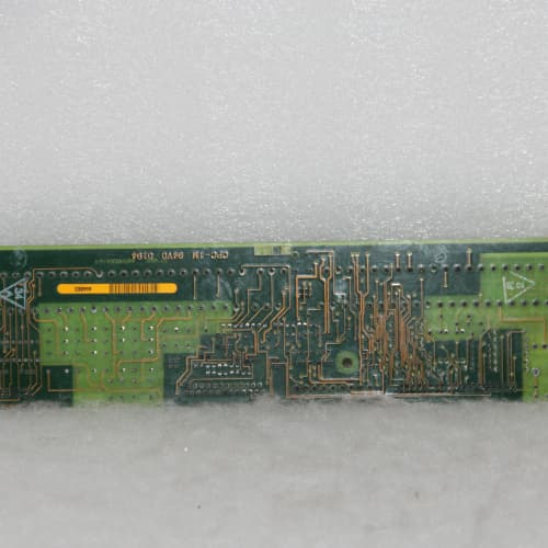
Description
Technical Parameters
-
Product Type: Resolver/encoder feedback terminal board
-
Resolver inputs: Sine, cosine, and reference (differential) – 6 terminals
-
Encoder inputs: A, B, Z (differential or single-ended) – 6 terminals
-
Tachometer input: ±10 VDC analog – 3 terminals
-
Cable fault detection: Enhanced – detects open-circuit, short-circuit, and signal loss (ADG1 specific)
-
Terminal type: Spring-clamp (push-in) – 24–16 AWG (solid or stranded with ferrule)
-
Current rating: 8 A per terminal
-
Isolation: 1500 Vrms between feedback inputs and drive logic
-
EMC filtering: Enhanced ferrite beads and capacitors on all inputs (ADG1 specific)
-
LED indicators: Power, Fault, and per-channel signal presence (sine/cosine/A/B/Z activity)
-
Connectors: One 26-pin header to regulator board (or to 531X156TRC/531X167MFR board); three 6-position terminal blocks
-
Mounting: 4× M4 holes (standard GE rack footprint)
-
Power supply: +5 VDC and +15 VDC from regulator board (or pass-through from 531X156TRC/531X167MFR)
-
Operating temperature: -10°C to 65°C
Advantages & Features
-
Spring-clamp terminals – Push-in wiring on GE 531X174RCCADG1 reduces installation time for resolver/encoder connections; no tools required for solid wire
-
Enhanced cable fault detection – Detects open-circuit, short-circuit, and signal loss on resolver/encoder wiring, simplifying troubleshooting and preventing unpredictable drive behavior
-
Per-channel LED indicators – Signal presence LEDs on GE 531X174RCCADG1 provide immediate visual confirmation of resolver sine/cosine and encoder A/B/Z activity, speeding up commissioning
-
Enhanced EMC filtering – Ferrite beads and capacitors on all inputs ensure reliable feedback in VFD-dense cabinets and high-EMI environments
-
Universal feedback support – Terminates resolvers, incremental encoders, and DC tachometers on the same board
-
Galvanic isolation – 1500 Vrms protects regulator board from feedback cable transients
-
Plug-and-play – Pin-compatible with earlier RCC revisions; no wiring changes needed
Application Cases
-
Rapid commissioning – System integrator used spring-clamp terminals on GE 531X174RCCADG1 for resolver wiring on 15 AC-300 drives; wiring time reduced by 40% compared to screw terminals
-
Fault diagnosis – Mining conveyor with long resolver cables used cable fault detection on GE 531X174RCCADG1 to pinpoint a broken sine wire, reducing troubleshooting from hours to minutes
-
High-EMI environment – Welding shop with 20+ arc welders used GE 531X174RCCADG1 for encoder feedback; enhanced EMC filtering eliminated speed feedback errors
Competitive Comparison
| Aspect | GE 531X174RCCADG1 (OEM) | Generic Replacement Feedback Terminal Board |
|---|---|---|
| Terminal type | Spring-clamp (tool-less, 24–16 AWG) | Screw terminals (requires tool) |
| Cable fault detection | Enhanced (open/short/signal loss) | None or basic |
| LED indicators | Per-channel signal presence | None |
| EMC filtering | Enhanced (ferrite + capacitors) | None or basic |
| Feedback types | Resolver, encoder, tachometer | Usually one type only |
| Installation speed | Fast (push-in wiring) | Moderate (screw tightening) |
Selection Suggestions
-
Choose GE 531X174RCCADG1 for rapid installation projects – spring-clamp terminals dramatically speed resolver/encoder wiring
-
Select ADG1 for long cable runs or hard-to-access installations – cable fault detection eliminates guesswork in wiring troubleshooting
-
For high-EMI environments (welding shops, VFD-dense cabinets), ADG1’s enhanced EMC filtering ensures reliable feedback
-
Verify your field wiring is within 24–16 AWG range (solid or stranded with ferrule) – GE 531X174RCCADG1 accepts most standard feedback cables
-
Confirm regulator board compatibility – works with 531X111, 531X139, and 531X305 series, typically connected via 531X156TRC or 531X167MFR interface boards
-
Prefer remanufactured units with spring-clamp terminals tested for retention force and LED function verified
Precautions
-
Always disconnect power before handling GE 531X174RCCADG1 – feedback cables may carry external voltages
-
For stranded wires on spring-clamp terminals, use ferrules to prevent strand fraying – exposed strands can short adjacent terminals
-
Insert wires fully until the wire stop is reached – partially inserted wires cause intermittent connections
-
Use shielded twisted-pair cables for resolver and encoder wiring – unshielded cables pick up EMI
-
Resolver excitation and feedback wires must be twisted pairs – separate excitation from feedback to avoid coupling
-
Encoder wiring requires proper termination – unterminated TTL encoders cause ringing and speed errors
-
The cable fault detection on GE 531X174RCCADG1 works only with properly terminated resolvers/encoders – unterminated wiring may trigger false faults
-
Per-channel LEDs indicate signal presence only – they do not verify signal quality (amplitude, phase, or noise)
-
For shielded cables, ground the shield at the drive end only (not at the feedback device) – prevents ground loops
-
Do not run feedback cables parallel to motor power leads – maintain at least 30 cm separation to avoid EMI
-
If a channel’s LED does not illuminate, check wiring continuity and polarity – reversed sine/cosine connections cause tracking failure
-
Do not use screwdrivers to force wires into spring-clamp terminals – using tools damages the spring mechanism
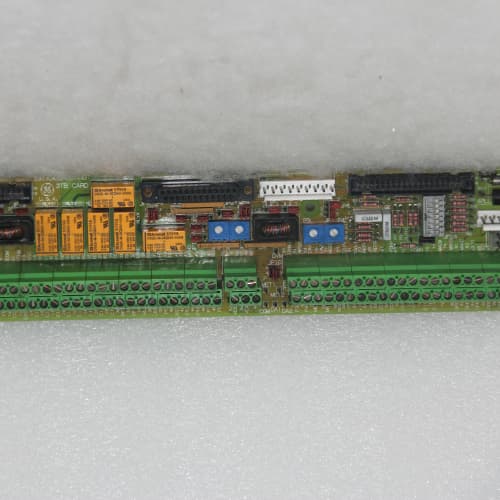
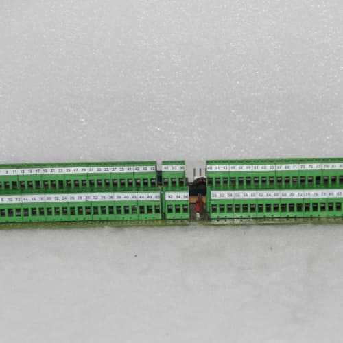
ABB 3BSE008572R1
ABB CI801
6EP1931-2DC21
SCHNEIDER 140CPS12400
.jpg)

Reviews
There are no reviews yet.