
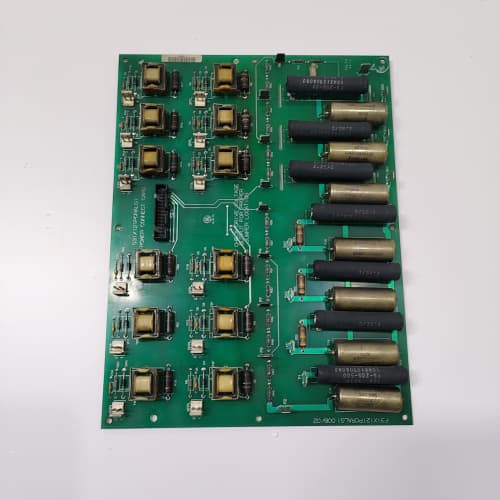
Description
Technical Parameters
-
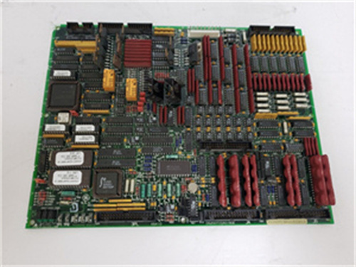
Product Type: Temperature monitoring terminal board
-
Temperature input channels: 8 differential (universal – thermocouple or RTD)
-
Sensor types: Thermocouple (J, K, T, E, S, R) or RTD (Pt100 / Pt1000) – software-configurable via drive parameters (no jumpers)
-
Cold-junction compensation: Enhanced onboard per-channel (accuracy: ±0.05%)
-
RTD excitation: Constant current source (software-selectable)
-
Input impedance: >10 MΩ (thermocouple mode)
-
Accuracy: ±0.05% of full scale
-
Surge protection: Enhanced TVS diodes (±4 kV surge rating – double standard)
-
Terminal type: Screw-type (unified across all channels) – 24–12 AWG
-
Current rating: 10 A per terminal
-
Isolation: 1500 Vrms between sensor inputs and drive logic
-
LED indicators: Power and per-channel status (signal presence/fault indication)
-
Connectors: One 26-pin header to regulator board (or to 531X155TXM board); two 12-position terminal blocks
-
Mounting: 4× M4 holes (standard GE rack footprint)
-
Power supply: +5 VDC and +15 VDC from regulator board (or pass-through from 531X155TXM)
-
Operating temperature: -20°C to 70°C (extended range)
-
Conformal coating: Marine-grade (moisture and corrosion resistant) – AFG2 specific
Advantages & Features
-
Unified screw terminals – All temperature inputs on GE 531X171TMAAFG2 use screw terminals, simplifying spare parts management and providing consistent high-retention performance for thermocouple/RTD wiring
-
Enhanced surge protection – ±4 kV TVS diodes on all temperature inputs protect GE 531X171TMAAFG2 and the regulator board from voltage spikes caused by lightning, inductive coupling, or electrostatic discharge
-
Software-configurable sensors – No hardware jumpers; sensor type set via drive parameters, reducing installation errors
-
Enhanced cold-junction compensation – ±0.05% accuracy for precision temperature measurement
-
Extended thermocouple support – Supports S and R types (up to 1760°C) for high-temperature applications
-
Per-channel LED indicators – Individual status LEDs provide immediate visual confirmation of signal presence/fault, simplifying troubleshooting
-
Marine-grade conformal coating – Protects GE 531X171TMAAFG2 from humidity, salt spray, and corrosive gases, making it suitable for offshore, marine, and chemical plant environments
-
Extended temperature range – -20°C to 70°C for harsh environments
-
Galvanic isolation – 1500 Vrms protects regulator board from sensor faults
-
Plug-and-play – Pin-compatible with ABG1/ABG2/ADG2/AEG2; no wiring changes needed
Application Cases
-
Lightning-prone offshore platform – Offshore drilling rig in Gulf of Mexico (frequent lightning strikes) used GE 531X171TMAAFG2 for motor bearing RTD monitoring; ±4 kV surge protection prevented sensor input failures that had plagued standard boards
-
High-EMI steel mill – Steel mill with large induction furnaces used GE 531X171TMAAFG2 for thermocouple monitoring; enhanced surge protection and conformal coating ensured reliable temperature readings in a high-noise, corrosive environment
-
Chemical plant with long cable runs – Chemical facility with 100-meter thermocouple runs used GE 531X171TMAAFG2; unified screw terminals allowed secure connection of heavy-gauge extension wire, while ±4 kV protection prevented induced voltage spikes from damaging the input circuitry
Competitive Comparison
| Aspect | GE 531X171TMAAFG2 (OEM) | Generic Replacement Temperature Terminal Board |
|---|---|---|
| Terminal type | Unified screw (24–12 AWG) | One type only (often limited gauge) |
| Surge protection | ±4 kV TVS (double standard) | ±2 kV typical or none |
| Sensor configuration | Software (no jumpers) | Hardware jumpers or fixed |
| Sensor types | J/K/T/E/S/R + Pt100/Pt1000 | Limited (J/K/T only typical) |
| CJC accuracy | ±0.05% | ±0.1–0.2% typical |
| LED indicators | Per-channel status | None |
| Temperature range | -20°C to 70°C | 0°C to 50°C typical |
| Conformal coating | Marine-grade | None or basic |
| Corrosion resistance | High (salt spray, chemicals) | Low to moderate |
Selection Suggestions
-
Choose GE 531X171TMAAFG2 for installations in lightning-prone regions (coastal areas, open terrain, offshore) or with long sensor cable runs – ±4 kV surge protection is essential
-
Select AFG2 for corrosive environments (chemical plants, marine, offshore) – conformal coating provides superior protection
-
For applications requiring unified screw terminals across all temperature inputs, AFG2 provides consistent wiring practices and simplified spare parts
-
For high-temperature applications (S/R thermocouples), AFG2’s software configuration supports these types
-
For troubleshooting convenience, per-channel LEDs on GE 531X171TMAAFG2 are a significant advantage – rapid fault identification without test equipment
-
Verify your field wiring is within 24–12 AWG range – GE 531X171TMAAFG2 accepts most standard thermocouple extension and RTD wires
-
Confirm regulator board firmware supports software sensor configuration – works with 531X111, 531X139, and 531X305 series (minimum firmware required)
-
Confirm compatibility with 531X155TXM temperature interface board – GE 531X171TMAAFG2 is designed to work with this board
-
Prefer remanufactured units with new cold-junction sensors, terminals tested, LED function verified, and conformal coating intact – any damage to the coating reduces corrosion protection
Precautions
-
Always disconnect power before handling GE 531X171TMAAFG2 – sensor wiring may carry external voltages
-
The enhanced surge protection (±4 kV) protects the board but does not eliminate the need for external surge suppressors on long cable runs – install additional protection at the sensor end for critical applications
-
When replacing with GE 531X171TMAAFG2, update drive parameters for sensor type selection – hardware jumpers are no longer used
-
Use thermocouple extension wire (not copper) from sensor to board – copper wire introduces measurement errors
-
For RTDs, use 3-wire or 4-wire configuration – 2-wire connections introduce significant measurement errors due to lead resistance
-
Keep sensor wiring away from power cables (IGBT, motor leads) to avoid EMI-induced false readings
-
Torque terminal screws to 0.5–0.6 N·m – over-tightening strips threads; under-tightening causes loose connections and intermittent readings
-
The per-channel CJC sensors are sensitive to airflow – do not mount GE 531X171TMAAFG2 directly in the path of cooling fans
-
Per-channel LEDs indicate signal presence only – they do not verify sensor calibration or measurement accuracy
-
Conformal coating protects the PCB but not the terminal screws – use corrosion‑resistant wire (tinned copper) to prevent galvanic corrosion at the terminal interface
-
For shielded cables, ground the shield at the sensor end only (or at the board – follow drive manual recommendations)
-
If a channel reads erratic, check sensor polarity – reversed thermocouple wiring gives negative readings
-
For long cable runs (>30m), use thicker gauge wire (lower resistance) to reduce error
-
Inspect conformal coating for scratches or cracks before installation – damaged coating exposes the PCB to corrosion and voids the protective feature of GE 531X171TMAAFG2
A-B 1769-OF4VI
GE IC200PBI001
POWERONE MAP55-4004


Reviews
There are no reviews yet.