
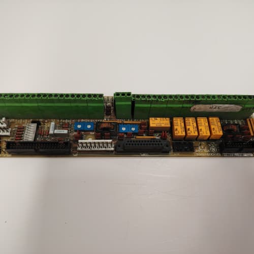
Description
Technical Parameters
-
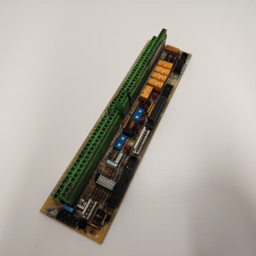
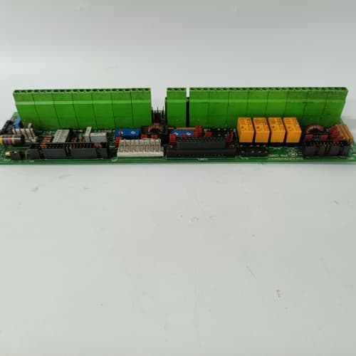
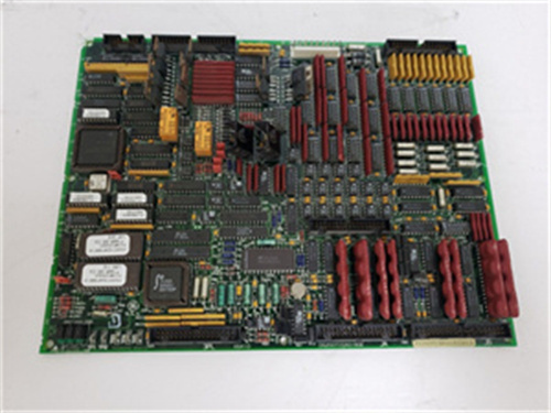
Product Type: Terminal board / field wiring termination assembly
-
Digital I/O terminals: 32 points (configurable via regulator board settings)
-
Analog I/O terminals: 12 points (voltage/current signals)
-
Communication terminals: 6 points (RS-485, RS-232)
-
Auxiliary power terminals: 6 points (120 VAC / 24 VDC)
-
Terminal type: Removable pluggable connectors (spring-clamp or screw-type)
-
Wire size: 0.2 – 2.5 mm² (24–12 AWG)
-
Current rating: 10 A per terminal (maximum)
-
Voltage rating: 300 VAC / 600 VAC (terminal-to-terminal)
-
Labeling: Enhanced silk-screen identification on GE 531X170TBSAAG1
-
Connectors: Two 34-pin headers to regulator board; one 26-pin header to auxiliary boards
-
Mounting: 4× M4 holes (standard GE rack footprint)
-
Operating temperature: 0°C to 60°C
Advantages & Features
-
Removable terminal blocks – Pluggable connectors on GE 531X170TBSAAG1 allow field wiring to remain intact while the board is replaced, significantly reducing downtime
-
Enhanced labeling – Clear, silk-screened identification for each terminal (e.g., DI1, AI1, COM) simplifies wiring and reduces commissioning errors
-
Flexible wiring – Accepts 24–12 AWG solid or stranded wire, compatible with most field devices
-
Clear signal grouping – Digital, analog, and power terminals are physically separated for easier troubleshooting
-
Plug-and-play – Direct replacement for earlier TBS revisions; no configuration changes needed
-
Durable construction – High-temperature-rated terminal blocks ensure long-term reliability
Application Cases
-
System upgrade – Plant replaced failed TBS board on AC-300 drive; removable terminal blocks on GE 531X170TBSAAG1 allowed wiring to stay connected, completing replacement in under 30 minutes
-
Commissioning support – Enhanced labeling on GE 531X170TBSAAG1 reduced wiring errors during new installation of 15 DC-300 drives, saving 2 days of commissioning time
-
Retrofit – Older TBS board with fixed terminals replaced by GE 531X170TBSAAG1; removable connectors simplified future maintenance and troubleshooting
Competitive Comparison
| Aspect | GE 531X170TBSAAG1 (OEM) | Generic Replacement Terminal Board |
|---|---|---|
| Terminal type | Removable pluggable (quick disconnect) | Fixed (screw terminals only) |
| Labeling | Enhanced silk-screen (clear IDs) | Basic or unlabeled |
| Wire size range | 24–12 AWG | Limited (18–14 AWG typical) |
| Connector durability | High-cycle rated (min 500 insertions) | Standard (50–100 cycles) |
| Isolation spacing | 8 mm creepage (UL/CSA compliant) | Varies (may not meet GE specs) |
Selection Suggestions
-
Choose GE 531X170TBSAAG1 for new installations or replacements – the removable terminal blocks are a major maintenance advantage over older fixed-terminal boards
-
Verify your field wiring is within 24–12 AWG range – GE 531X170TBSAAG1 accepts most standard industrial wires
-
Confirm regulator board compatibility – works with 531X111, 531X139, and 531X305 series
-
Prefer remanufactured units with all terminal blocks intact and tested for continuity – loose or damaged terminals cause intermittent faults
-
For critical signals (analog, communication), use twisted-pair cables and route separately from power wiring
Precautions
-
Always disconnect power before handling GE 531X170TBSAAG1 – field wiring may carry high AC voltages
-
Do not exceed 10 A per terminal – higher current damages the terminal block and PCB traces
-
Verify wire insulation rating meets 300 VAC minimum – underrated insulation may arc between terminals
-
When replacing, label all field wiring before removing the old board – even with removable connectors, mislabeling causes commissioning delays
-
Torque terminal screws to manufacturer specification (typically 0.5–0.6 N·m) – over-tightening strips threads; under-tightening causes loose connections and overheating
-
Use ferrules on stranded wires to prevent strand fraying – exposed strands can short adjacent terminals on GE 531X170TBSAAG1
-
Maintain separation between high-voltage and low-voltage wiring in the terminal blocks – 8 mm creepage distance must be maintained
-
When using removable connectors, insert them firmly until the latch clicks – partially inserted connectors cause intermittent contact
-
For analog signals, use shielded cables and ground the shield at the drive end only – reduces EMI-induced errors
Bently Nevada 125720-01
A-B 1756-A13
YASKAWA SGMAH-04AAA61D-OY
A-B 1756-PA72


Reviews
There are no reviews yet.