
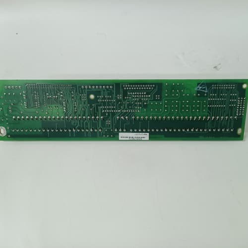
Description
Technical Parameters
-
Product Type: Motor feedback / resolver interface board
-
Resolver inputs: Sine, cosine, and reference (differential, high-impedance)
-
Resolver excitation: 4 Vrms / 2–10 kHz (programmable frequency)
-
Resolver-to-digital conversion: Onboard RDC with 16-bit resolution (absolute position)
-
Velocity resolution: 16-bit (0.005 RPM at typical speeds)
-
Position accuracy: ±0.05° electrical
-
Cable fault detection: Detects open-circuit, short-circuit, and signal loss on resolver wiring (ALG1 enhanced)
-
Input impedance: >500 kΩ (sine/cosine)
-
Isolation: 1500 Vrms between resolver inputs and drive logic
-
Connectors: One 26-pin header to regulator board; one 10-pin terminal block for resolver wiring
-
Mounting: 4× M4 holes (standard GE rack footprint)
-
Power supply: +5 VDC and +15 VDC from regulator board
-
Operating temperature: -20°C to 70°C (extended)
-
LED indicators: Power, Fault, Lock (RDC tracking), and Cable Fault (ALG1 enhanced)
Advantages & Features
-
Integrated resolver-to-digital converter – No external RDC modules required; GE 531X167MFRALG1 directly interfaces with resolvers for absolute position feedback
-
Cable fault detection – Enhanced ALG1 revision detects open-circuit, short-circuit, and signal loss on resolver wiring, preventing unpredictable drive behavior and simplifying troubleshooting
-
Extended temperature range – -20°C to 70°C rating for unheated cabinets or high-ambient environments
-
Programmable excitation frequency – Adjustable 2–10 kHz to match any resolver specification and compensate for long cable capacitance
-
High-resolution feedback – 16-bit position and velocity data for precision torque and speed control
-
Diagnostic LEDs – “Lock” LED indicates RDC tracking; “Cable Fault” LED provides immediate wiring fault indication
-
Plug-and-play – Pin-compatible with earlier MFR revisions
Application Cases
-
Wind turbine pitch control – Resolver feedback on pitch motors exposed to -20°C; GE 531X167MFRALG1 extended temperature rating ensured reliable operation in cold climates
-
Long cable installations – Mining conveyor with 150-meter resolver cables used GE 531X167MFRALG1 cable fault detection to pinpoint a broken wire, reducing troubleshooting time from hours to minutes
-
Servo positioning – CNC machine used GE 531X167MFRALG1 for resolver-based absolute position feedback, providing 0.05° accuracy for precision cutting
Competitive Comparison
| Aspect | GE 531X167MFRALG1 (OEM) | Generic Aftermarket Resolver Card |
|---|---|---|
| Cable fault detection | Yes (open/short/signal loss) | None |
| Temperature range | -20°C to 70°C | 0°C to 50°C typical |
| Resolver excitation | Programmable 2–10 kHz | Fixed frequency only |
| Position resolution | 16-bit | 10–12 bit typical |
| Isolation | 1500 Vrms | Usually non-isolated |
| Diagnostic LEDs | Lock + Cable Fault | Limited or none |
Selection Suggestions
-
Choose GE 531X167MFRALG1 over earlier MFR revisions for remote or hard-to-access installations – cable fault detection eliminates guesswork in wiring troubleshooting
-
Select ALG1 for unheated locations, outdoor enclosures, or high-ambient environments (>50°C)
-
Verify your resolver’s excitation voltage and frequency requirements – GE 531X167MFRALG1 provides programmable frequency but fixed 4 Vrms output
-
Confirm regulator board compatibility – works with 531X111, 531X139, and 531X305 series (firmware must support MFR boards)
-
For long cable runs (>50m), use the programmable excitation to compensate for capacitance – start at 2 kHz and adjust based on signal quality
-
Prefer remanufactured units with new RDC chips and optocouplers
Precautions
-
Always disconnect power before handling GE 531X167MFRALG1 – resolver wiring carries AC excitation voltage
-
Use shielded twisted-pair cables for resolver wiring (sine, cosine, and reference) – unshielded cables pick up EMI
-
Excitation wiring must be shielded separately from feedback wiring – coupling between excitation and feedback introduces measurement errors
-
The cable fault detection on GE 531X167MFRALG1 works only with properly terminated resolvers – unterminated wiring may trigger false faults
-
When replacing, transfer all resolver parameters (pole count, excitation frequency, offset angle) to the new GE 531X167MFRALG1 via drive software
-
Torque mounting screws to 2–3 N·m – over-tightening cracks the PCB
-
If the “Lock” LED is off, check resolver wiring continuity and polarity – reversed sine/cosine connections cause tracking failure
-
The “Cable Fault” LED indicates a wiring problem – check for open circuits, shorts, or moisture ingress first
-
For resolver installations, ground the cable shield at the drive end only – dual-ended grounding creates ground loops
-
Do not run resolver cables parallel to motor power leads – maintain at least 30 cm separation to avoid EMI
SCHNEIDER ATV58HD12N4
A-B 1756-A13
AB 1746-INT4
WESTINGHOUSE 5X00121G01
Reviews
There are no reviews yet.