
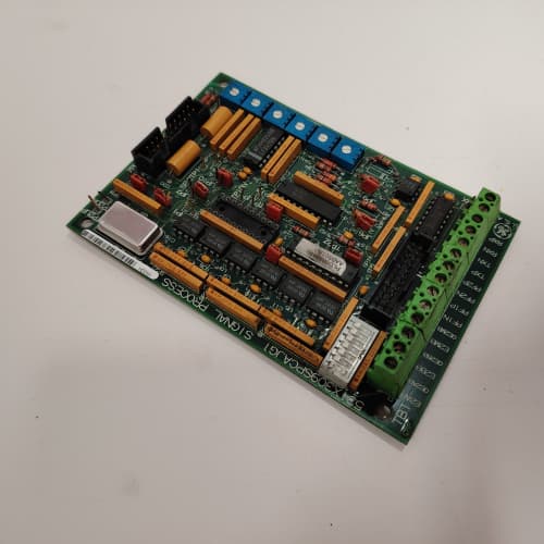
Description
Technical Parameters
-
Product Type: Multi-purpose I/O expansion board (relay output version)
-
Digital inputs: 8 (24 VDC, opto-isolated, software-configurable as sinking or sourcing)
-
Digital outputs: 8 (relay outputs – Form A, 2A @ 30 VDC / 250 VAC, normally-open)
-
Relay contact rating: 2A (resistive), 0.5A (inductive)
-
Analog inputs: 4 differential (software-configurable: ±10V, 0–10V, 0–20mA, 4–20mA)
-
Analog outputs: 2 (0–10V or 4–20mA, software-selectable, 12-bit resolution)
-
I/O configuration: Per-channel software assignment – no jumpers required
-
Transient protection: Enhanced TVS diodes on all I/O points (±2 kV surge rating)
-
Isolation: 1500 Vrms between I/O and drive logic (2500 Vrms on relay contacts)
-
Connectors: One 26-pin header to regulator board; two 12-position terminal blocks for field wiring
-
Mounting: 4× M4 holes (standard GE rack footprint)
-
Power supply: +5 VDC and +15 VDC from regulator board
-
LED indicators: Power, Fault, and individual status LEDs for each digital I/O point
Advantages & Features
-
Relay outputs – 8 Form A relays handle higher current (2A) and AC loads, eliminating external interposing relays for most applications; GE 531X159MPEARG1 is ideal for direct contactor and solenoid control
-
Extended analog input range – ±10V input supports bipolar transducers (e.g., bidirectional torque or position sensors)
-
Enhanced transient protection – TVS diodes on all I/O points protect GE 531X159MPEARG1 from voltage spikes generated by inductive loads
-
Software-configurable I/O – Each digital point can be independently set as input or output via drive parameters, reducing spare board variety
-
Flexible analog ranges – 4 analog inputs accept voltage or current without hardware changes; 2 analog outputs selectable for 0–10V or 4–20mA
-
Galvanic isolation – 1500 Vrms protects regulator board from field wiring faults; 2500 Vrms on relay contacts
-
Diagnostic LEDs – Individual status LEDs for each digital point simplify troubleshooting
Application Cases
-
Motor starter control – Conveyor system used GE 531X159MPEARG1 relay outputs to directly energize 120V AC motor contactors (1.5A coil current), eliminating 8 interposing relays and saving panel space
-
Solenoid valve control – Hydraulic press used GE 531X159MPEARG1 to control 24V DC solenoid valves; the relay outputs handled inrush current without failure
-
Bipolar sensor integration – Test stand with bidirectional torque transducer (±10V) used the extended analog input range on GE 531X159MPEARG1 for precise measurement of clockwise and counterclockwise torque
Competitive Comparison
| Aspect | GE 531X159MPEARG1 (OEM) | Generic Aftermarket I/O Card |
|---|---|---|
| Digital output type | Relay (2A, AC/DC) | Transistor (0.5A, DC only) |
| Transient protection | ±2 kV TVS on all I/O | Limited or none |
| Analog input range | ±10V, 0–10V, 0/4–20mA | 0–10V or 4–20mA only |
| Relay contact rating | 2A resistive / 0.5A inductive | 1A typical |
| Isolation (relay) | 2500 Vrms | 1500 Vrms typical |
| Diagnostic LEDs | Per-point status | Limited or none |
Selection Suggestions
-
Choose GE 531X159MPEARG1 over AMG1 (transistor outputs) when controlling AC loads (contactors, solenoids) or loads >0.5A – the relay outputs handle higher current and AC directly
-
Select ARG1 for bipolar sensor applications requiring ±10V analog inputs
-
Verify load current and voltage before connecting to relay outputs – GE 531X159MPEARG1 relays are rated 2A resistive; inductive loads require derating to 0.5A
-
Confirm regulator board compatibility – works with 531X111, 531X139, and 531X305 series (firmware must support ARG1)
-
For critical applications, consider using external surge suppressors on relay contacts when switching inductive loads (contactors, solenoids) – the internal TVS protects the board, not the contacts
-
Prefer remanufactured units with new relay assemblies (mechanical wear is common on used boards)
Precautions
-
Always disconnect power before handling GE 531X159MPEARG1 – field wiring may carry lethal AC voltages
-
Do not exceed 2A on relay contacts – higher current welds the contacts and permanently damages the board
-
Inductive loads (contactors, solenoids) require external flyback diodes (DC) or snubbers (AC) across the coil – the internal TVS protects the board, not the relay contacts from arcing
-
Relay contacts are normally-open only – if normally-closed contacts are required, use an external relay
-
Analog inputs in current mode require the internal 250Ω resistor – do not add external resistors
-
When replacing, transfer all I/O configuration parameters from the old GE 531X159MPEARG1 to the new board via drive software
-
Torque mounting screws to 2–3 N·m – over-tightening cracks the PCB
-
Relay life is finite – for high-cycle applications (>100,000 operations), consider external solid-state relays to extend board lifespan
-
If a relay output does not activate, check the output configuration (input vs. output) in drive parameters – the software assignment overrides physical wiring
-
Do not mix AC and DC loads on the same relay bank without verifying proper isolation – keep AC wiring separate from DC/analog wiring in the cabinet
AB 1746-NO4V
SIEMENS 6ES7322-1HH01-0AA0
A-B 1783-US6T2F
A-B 1756-PA72



Reviews
There are no reviews yet.