
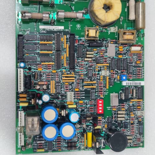
Description
Technical Parameters
-
Product Type: Speed feedback / encoder interface board
-
Input types: Incremental encoder (TTL/HTL), resolver (sine/cosine), DC tachometer (analog voltage) – selectable via jumpers
-
Encoder channels: A, B, Z (differential or single-ended) with optional index pulse
-
Resolver excitation: 4 Vrms / 3–10 kHz (programmable)
-
Tachometer input: ±10 VDC or ±20 mA (selectable)
-
Maximum encoder frequency: 1 MHz (500 kHz per channel)
-
Resolution: 16-bit velocity/position data to regulator
-
Scaling: Programmable pulses per revolution (1–65535) via drive parameters
-
Isolation: 1500 Vrms between feedback inputs and drive logic
-
Connectors: One 26-pin header to regulator board; one 15-pin D-sub (encoder); one 6-pin terminal block (resolver/tachometer)
-
Mounting: 4× M4 holes (standard GE rack footprint)
-
Power supply: +5 VDC and +15 VDC from regulator board
-
LED indicators: Power, Fault, and A/B/Z channel activity
Advantages & Features
-
Universal input flexibility – Supports encoder, resolver, or DC tachometer on the same board; GE 531X156TECABG1 adapts to existing feedback devices without hardware changes
-
High-frequency response – 1 MHz maximum input for high-speed spindle and servo applications
-
Programmable pulse scaling – Match any motor/encoder combination without changing hardware
-
Resolver excitation – Onboard oscillator generates excitation for resolver feedback
-
Galvanic isolation – 1500 Vrms protects regulator board from feedback cable transients
-
Diagnostic LEDs – Channel activity and fault indicators for rapid troubleshooting
-
Plug-and-play – Direct replacement for earlier TEC revisions
Application Cases
-
High-speed spindles – CNC machining center used GE 531X156TECABG1 with 5000 PPR encoder for precise speed control up to 15,000 RPM
-
Hoist positioning – Overhead crane with resolver feedback on AC-300 drive; the resolver excitation on GE 531X156TECABG1 eliminated the need for external signal conditioner
-
Web tension control – Printing press retrofitted with DC tachometer; the universal input of GE 531X156TECABG1 replaced a failed tachometer interface without changing the feedback device
Competitive Comparison
| Aspect | GE 531X156TECABG1 (OEM) | Generic Aftermarket Encoder Card |
|---|---|---|
| Input types | Encoder, resolver, tachometer (selectable) | Encoder only |
| Max encoder frequency | 1 MHz | 100–500 kHz typical |
| Resolver excitation | Onboard (no external required) | Requires external exciter |
| Pulse scaling | Programmable (1–65535) | Fixed or limited range |
| Isolation | 1500 Vrms | Usually non-isolated |
| Diagnostics | A/B/Z activity LEDs | Limited or none |
Selection Suggestions
-
Verify your feedback device type (encoder, resolver, or tachometer) – GE 531X156TECABG1 supports all but requires correct jumper settings
-
Confirm encoder voltage level (TTL 5V vs. HTL 24V) – the board accepts both but jumper selection is required
-
Check regulator board compatibility – works with 531X111, 531X139, and 531X305 series
-
For high-speed applications (>5000 RPM), verify your encoder frequency does not exceed the 1 MHz limit of GE 531X156TECABG1
-
Prefer remanufactured units with new optocouplers and capacitors
Precautions
-
Always disconnect power before handling GE 531X156TECABG1 – feedback cables may carry external voltages
-
Use shielded twisted-pair cables for encoder/resolver wiring – unshielded cables cause noise-induced speed errors
-
Verify encoder power supply (5V or 24V) matches your encoder requirements – incorrect voltage damages the encoder or the board
-
When replacing, transfer all jumper settings (input type, voltage level) to the new GE 531X156TECABG1
-
Resolver excitation wiring requires twisted pairs for excitation and feedback – use dedicated shielded cable
-
Torque mounting screws to 2–3 N·m – over-tightening cracks the PCB
-
If speed feedback is erratic, check the shield grounding – ground the shield at the drive end only
-
Do not run feedback cables parallel to motor power leads – maintain at least 30 cm separation to avoid EMI
A-B 1794-OB8EP
A-B 1756-A13
SCHNEIDER 140CPS11410
A-B 1766-L32BXBA


Reviews
There are no reviews yet.