
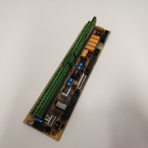
Description
Technical Parameters
-
Microcontroller: Custom GE ASIC at 16 MHz, 2.0 ms scan cycle
-
Analog Inputs: 4 differential channels, ±10V/0–10V/4–20mA, >18 MΩ impedance
-
Analog Outputs: 2 isolated, 0–10V/4–20mA, 500 Hz update with slew-rate limiter and clamping
-
Digital I/O: 8 inputs (24V DC), 6 transistor outputs (24V DC, 0.5A) with short-circuit protection
-
Encoder Input: Dedicated differential encoder channel (TTL/HTL, up to 500 kHz) – new on this revision
-
Onboard Pots: 12 trim-pots including gain, offset, servo stiffness, tachometer damping, current loop stability, and encoder blending
-
Status LEDs: Red/green/yellow/blue array with 32 fault codes (5-bit)
-
Operating Temp: 0°C to +65°C
-
Humidity: 5–95% non-condensing with triple-conformal coating
Key Advantages
-
Dual Feedback Support: The 531X133PRUAGG1 accepts both analog tachometer (3V p-p minimum) and digital encoder inputs, with automatic or manual blending between the two for optimal speed control
-
Encoder Blending Control: Dedicated potentiometer allows smooth transition from tachometer to encoder feedback, enabling precise low-speed regulation
-
Current Loop Stability: Dedicated pot for optimizing response across different motor inductances
-
Output Clamping: Prevents overcurrent during transient conditions
-
Auto-Tuning: Factory-enabled self-calibration routine
-
Thermal Derating: Clock reduction above 60°C prevents catastrophic failure
-
Fieldbus Ready: 10-pin header for Profibus, DeviceNet, or Modbus TCP gateways
-
32 Diagnostic Codes: Includes encoder fault, tachometer loss, current saturation, and field weakening faults
Applications
-
Steel/aluminum rolling mills
-
Paper/tissue machines
-
Wire drawing and cable extrusion
-
Mine hoists and slope conveyors
-
Marine propulsion
-
Test dynamometers
-
Printing presses
-
High-precision positioning systems (with encoder feedback)
Comparison with Alternatives
| Aspect | 531X133PRUAGG1 | 531X133PRUAFG1 | Siemens 6RA80 | ABB DCS800 |
|---|---|---|---|---|
| Tach Sensitivity | 3V p-p | 3V p-p | Digital only | Digital only |
| Encoder Input | Yes (dedicated) | No | Yes (integrated) | Yes (integrated) |
| Feedback Blending | Yes (manual pot) | No | Yes (software) | Yes (software) |
| Auto-Tuning | Yes | Yes | Yes | Yes |
| Output Clamping | Yes | Yes | Yes | Yes |
| Fault Codes | 32 | 32 | 100+ | 100+ |
| Fieldbus Header | Yes | Yes | Integrated | Integrated |
| Drop-in Fit | Late DC300 | Late DC300 | Full swap | Full swap |
| Availability | Very scarce | Scarce | Active | Active |
Selection & Sourcing Precautions
-
Verify Revision: Confirm “GG1” suffix, firmware checksum, and test report—do not accept FG1 or earlier
-
Inspect Capacitors: Check for bulging/leaking on all electrolytic units
-
Check Pots: Ensure all 12 trim-pots rotate smoothly; encoder blending pot is new—verify operation
-
Encoder Header: Inspect dedicated encoder connector for bent or corroded pins
-
Test Documentation: Demand linearity (<0.1%), output accuracy (<0.15%), tach sensitivity (3V p-p), encoder input functional test, auto-tuning verification, and 48-hour burn-in at 60°C
-
Warranty: Minimum 2 years; prefer 3–5 years due to scarcity
-
ESD Handling: Anti-static bags only; use grounded wrist strap
Installation Precautions
-
Discharge Bus: Confirm <5V on DC terminals before insertion
-
ESD Protocol: Wrist strap and ESD mat mandatory
-
Cable Separation: Maintain 300 mm between feedback and power cables
-
Record Pot Settings: Transfer 12 pot values from old board as starting point
-
Encoder Wiring: Use shielded twisted-pair cable; connect shield to ground at drive end only
-
Feedback Blending: Set encoder blending pot based on application—full tach for high-speed, full encoder for low-speed/positioning, midpoint for mixed operation
-
Tune Current Loop: Adjust stability pot using oscilloscope for critical damping
-
Auto-Tuning: Apply digital input sequence; uncouple motor from load
-
Tach Damping: Set based on cable length—<30m minimum, 30–60m midpoint, >60m maximum
-
Output Clamp: Do not set below 80% of max firing command
-
Gateway Module: Power off before connecting to 10-pin header
-
Firmware Lock: Do not attempt reprogramming—will brick the board
-
Regular Inspection: Visual check every 6 months; clean dust with compressed air
A-B 1756-PB75
Schneider 140CPS12420
A-B 1756-OF8
SCHNEIDER 140NOE77101


Reviews
There are no reviews yet.