
")
Description
Product Overview and Description
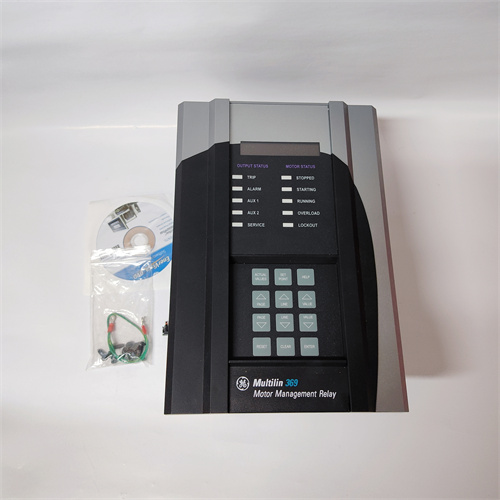
The GE 369-HI-0-M-F-E-0 is a specific configuration of the GE Multilin 369 Motor Management Relay, a sophisticated digital protection and management device designed for medium-voltage and high-performance low-voltage motors. This is not a standard PLC I/O module but a critical, intelligent field device that connects to a control system to provide comprehensive protection, monitoring, and diagnostics for critical motors, pumps, fans, and compressors. The suffix HI-0-M-F-E-0 denotes a precise hardware and functional configuration, indicating options such as a high-resolution display, specific communication modules, and input/output types. The core function of the GE 369-HI-0-M-F-E-0 is to continuously monitor motor current, voltage, temperature, and other parameters to protect against faults like overload, phase loss, stall, jam, ground fault, and under/over current. By integrating this relay into an automation network, operators gain deep insight into motor health and performance, enabling predictive maintenance and reducing unplanned downtime. The versatility and reliability of the GE Multilin 369, in this specific configuration, make it an industry-standard solution for managing expensive and process-critical rotating assets.
Product Parameters and Specifications
-
Product Type: Digital Motor Management Relay / Intelligent Electronic Device (IED)
-
Manufacturer Part Number (MPN): 369-HI-0-M-F-E-0
-
Brand: GE (now part of GE Vernova, under the Grid Solutions business)
-
Series: Multilin 369
-
Configuration Code Breakdown (Typical Interpretation):
-
HI: High-Resolution, Backlit Graphical Display.
-
0: Specific hardware revision or option.
-
M: Modbus RTU communication protocol (RS-485).
-
F: Form C (SPDT) output relay configuration.
-
E: 100-240V AC/DC power supply.
-
0: Standard enclosure type.
-
-
Protection Functions: Overload (49), Thermal Capacity (49RMS), Locked Rotor / Stall (48), Jam (undercurrent), Phase Unbalance (46), Ground Fault (50G/51G), Start Protection, Short Circuit (50).
-
Monitoring: True RMS measurements (current, voltage, power, power factor, energy), thermal capacity used, starts per hour, running time, torque.
-
Inputs: Current Transformer (CT) inputs (typically 3 phase + ground), voltage inputs (optional), RTD/thermocouple inputs for direct motor winding/bearing temperature.
-
Outputs: Programmable Form C relay outputs for trip, alarm, or control; analog output (4-20mA).
-
Communication: As per “M” code, includes Modbus RTU via RS-485. Other variants support PROFIBUS DP, DeviceNet, or Ethernet.
Key Advantages and Features
The GE 369-HI-0-M-F-E-0 offers advanced motor protection that goes far beyond simple overload relays. Its key advantage is the use of a detailed thermal model that accurately calculates the heating and cooling of the motor based on actual load current and motor data, providing precise overload protection and preventing premature insulation failure. The high-resolution display offers clear, real-time data and intuitive menu navigation for local diagnostics. The integrated Modbus communication allows for seamless integration into PLC or SCADA systems for centralized monitoring and control. Its comprehensive suite of programmable protection functions in a single device reduces panel space and wiring complexity. The relay also provides valuable maintenance data, such as starts-to-failure estimates and thermal capacity used, enabling condition-based maintenance strategies. The rugged design of the GE Multilin 369 ensures reliable operation in harsh industrial electrical environments.
Application Scenarios and Use Cases
The GE 369-HI-0-M-F-E-0 is deployed wherever critical motors drive essential processes. In water and wastewater treatment plants, it protects and monitors large raw water intake pumps, aerator blowers, and sludge centrifuges. In the oil & gas industry, it is used on pipeline booster pumps, gas compressor motors, and drilling rig mud pumps. For mining and minerals processing, it safeguards crusher motors, conveyor drives, and ball mill motors. In power generation, it is applied to boiler feed pumps, induced draft (ID) and forced draft (FD) fans, and cooling water pumps. The Modbus RTU communication of this specific 369-HI-0-M-F-E-0 configuration makes it ideal for integration into legacy or cost-effective control systems where motor data needs to be aggregated by a central RTU or PLC for system-wide supervision and data logging.
Comparison with Competing Products
Compared to basic thermal overload relays or simple motor protection circuit breakers, the GE 369-HI-0-M-F-E-0 is in a different class, offering digital intelligence, communication, and detailed diagnostics. It competes directly with other digital motor management relays such as the Siemens SIMOCODE pro, the ABB M102/M201, or the Eaton EMR3. The GE Multilin 369 series is often regarded for its particularly robust thermal model and its heritage in heavy industry applications. Compared to more basic motor protection relays, the 369-HI-0-M-F-E-0 provides a higher level of integration and data visibility. Versus full-featured protective relays (like the GE Multilin 869), the 369 is more focused specifically on motor protection rather than general feeder or generator protection, offering a more cost-optimized and application-tailored feature set.
Selection Guidelines and Important Notes
Selection Advice:
-
Match Motor Specifications: The GE 369-HI-0-M-F-E-0 must be configured with the exact Full Load Amps (FLA), service factor, and thermal limits of the motor it is protecting. Incorrect motor data entry will compromise protection.
-
Verify CT Ratios: Ensure the current transformers (CTs) installed in the motor circuit have a ratio compatible with the relay’s input range. The relay settings must match the CT ratio.
-
Confirm Communication Needs: This specific variant has Modbus RTU. Ensure your controlling PLC or SCADA master has an available RS-485 port and supports Modbus protocol. For other networks (PROFIBUS, Ethernet), a different suffix is required.
-
Assess Input Requirements: Determine if you need direct temperature monitoring via RTDs. This may require an additional RTD input module for the 369 relay.
-
Plan for Programming: You will need access to GE’s EnerVista 369 Setup software for detailed configuration, although basic settings can be made via the front panel.
Important Precautions:
-
De-energize Before Installation: Always ensure the motor starter and control circuit are completely de-energized before wiring the GE 369-HI-0-M-F-E-0.
-
CT Circuit Safety: Never open the secondary circuit of a current transformer (CT) while it is energized. This can produce dangerously high voltages. The CT inputs to the 369 relay must be shorted if disconnected.
-
Accurate Motor Modeling: The effectiveness of the thermal overload protection is entirely dependent on the accuracy of the entered motor parameters. Obtain these from the motor nameplate or manufacturer.
-
Functional Testing: After configuration, perform a full functional test of the trip and alarm outputs using secondary injection (simulating fault currents) to verify correct operation before placing the motor in service.
-
Firmware and Software: Keep the relay’s firmware and the EnerVista software up to date for access to the latest features and bug fixes. Always back up the configuration file.
-
Environmental Ratings: Install the relay in an enclosure or location that respects its specified temperature, humidity, and pollution degree ratings.
DSRB110
DSPX3221
DSPC3221
DSPC3122
DSPC3121

Reviews
There are no reviews yet.